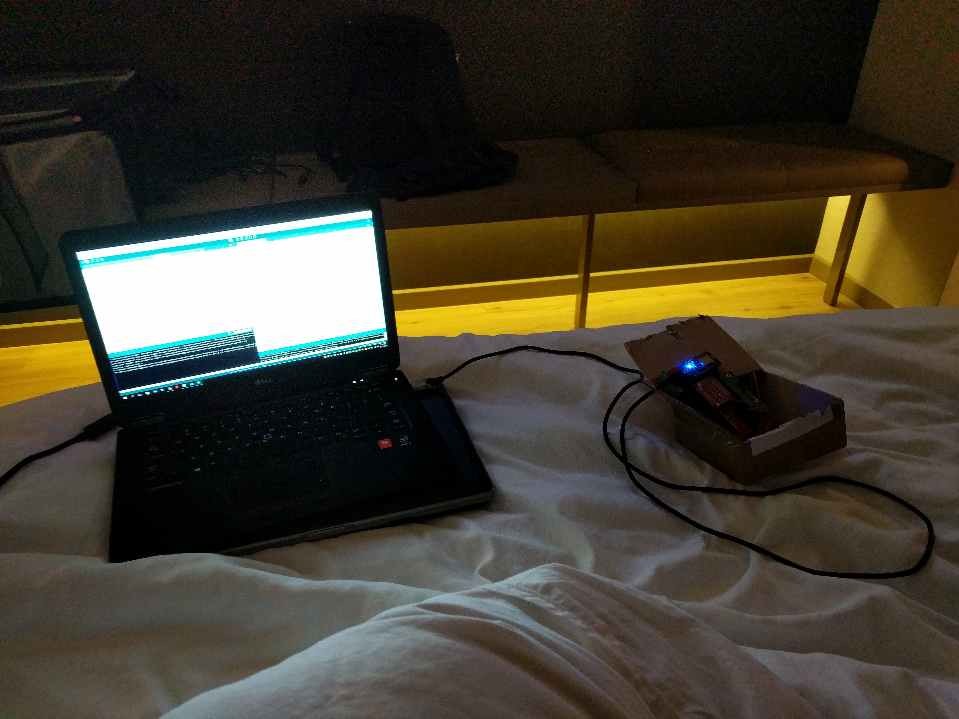
I took the controller with me on a business trip and spend the night getting the basic code framework out. It is going to run on top of Arkhipenko’s TaskScheduler. (https://github.com/arkhipenko/TaskScheduler) This should help me isolate any issues between the different control systems while managing the different task’s timing requirements. The code will be divided up into 5 major systems with the major systems having some subsystems
- GPI control/logic – will monitor the inputs and sent internal flags based on their states
- Sub System – MCP monitor – will check to make sure the MCP23017 chip(s) is responding to command correctly, if not put the system into a failed state.
- Motor control/logic – will monitor the internal flags and set the relay or IR pules that will control the motor
- LCD control – will decide what should be display
- Sub System – LED Display – will perform the LCD updates based on the internal flags of LCD control. It is in its own task because the LCD is I2C and want it to have the lowest priority and could be missed a few loops if more import task needs to run.
- Serial Debug – TBD – will be used to debug the system
- WiFi Web Server - TBD – To control internal settings
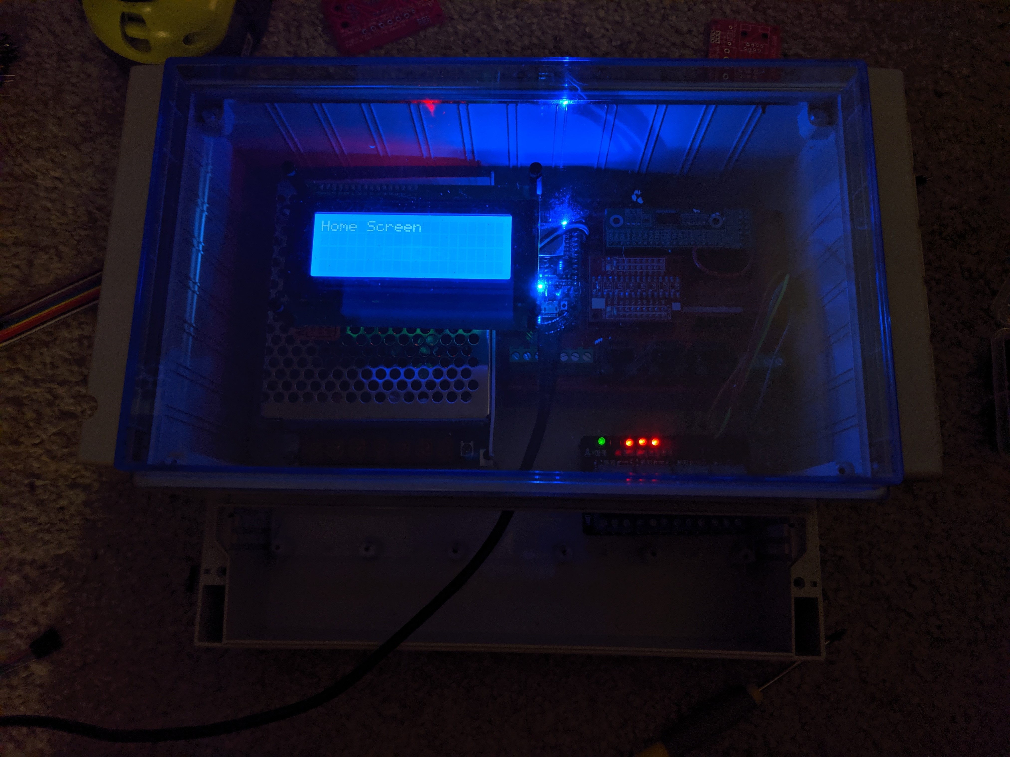
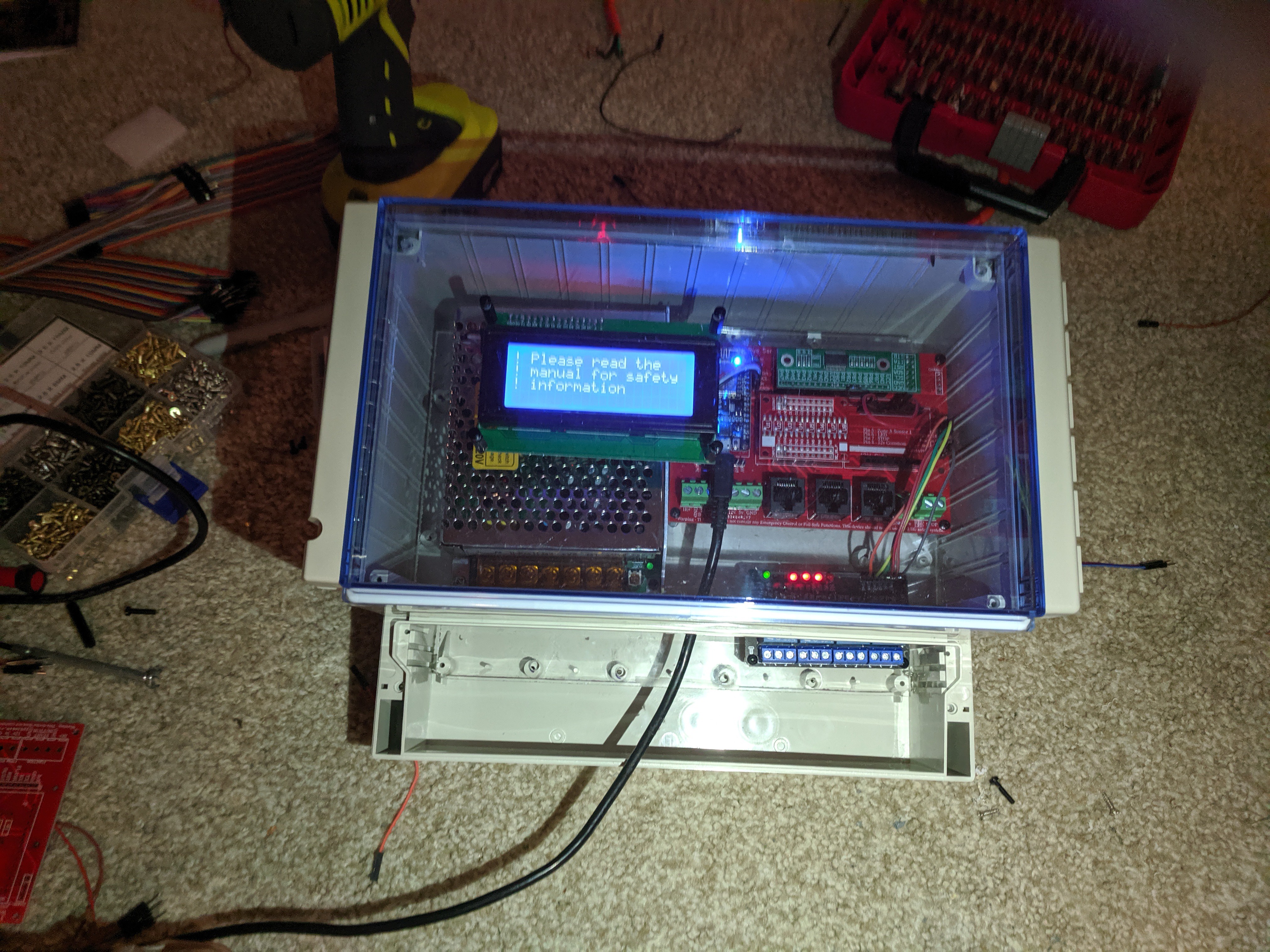
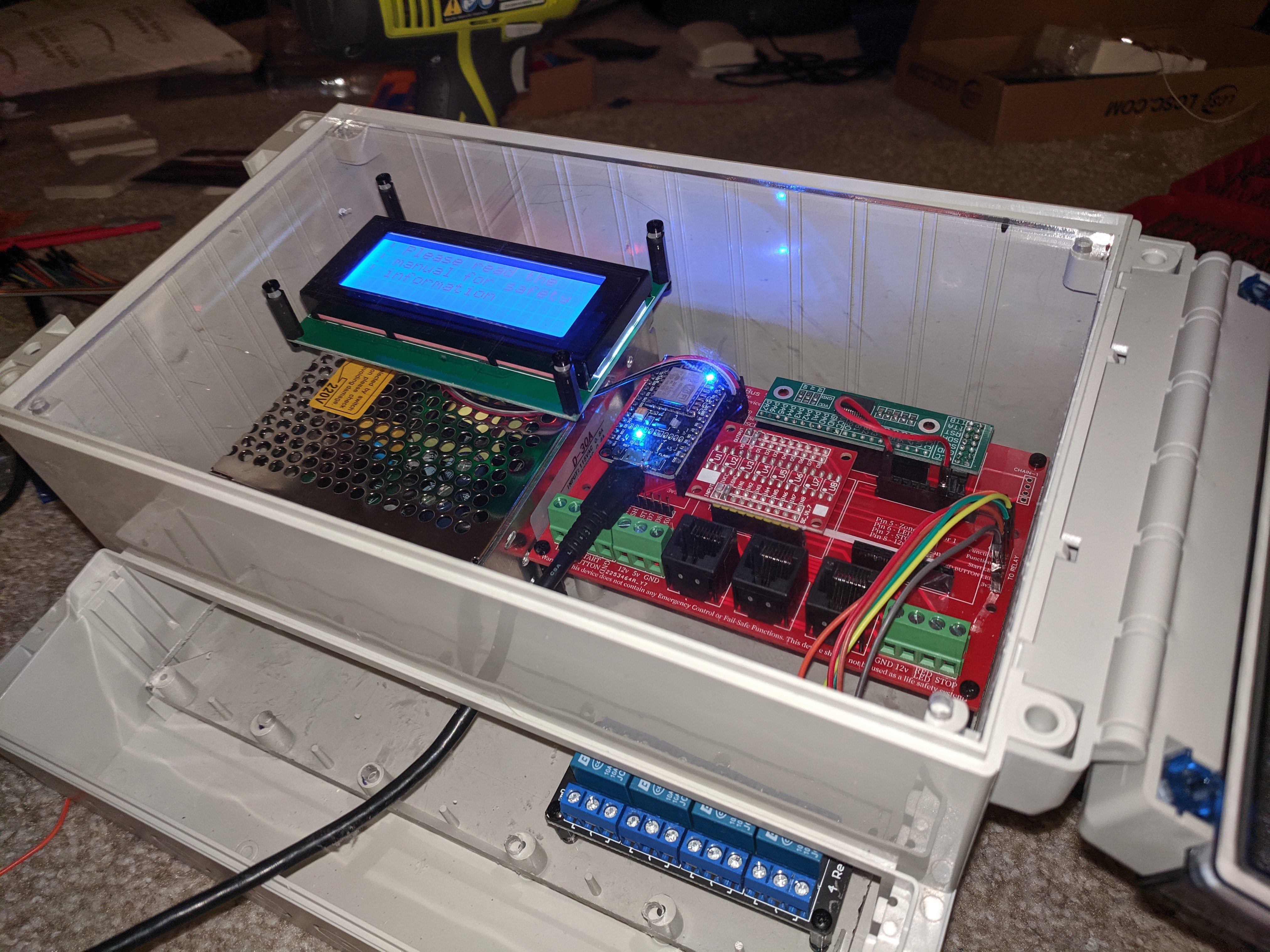
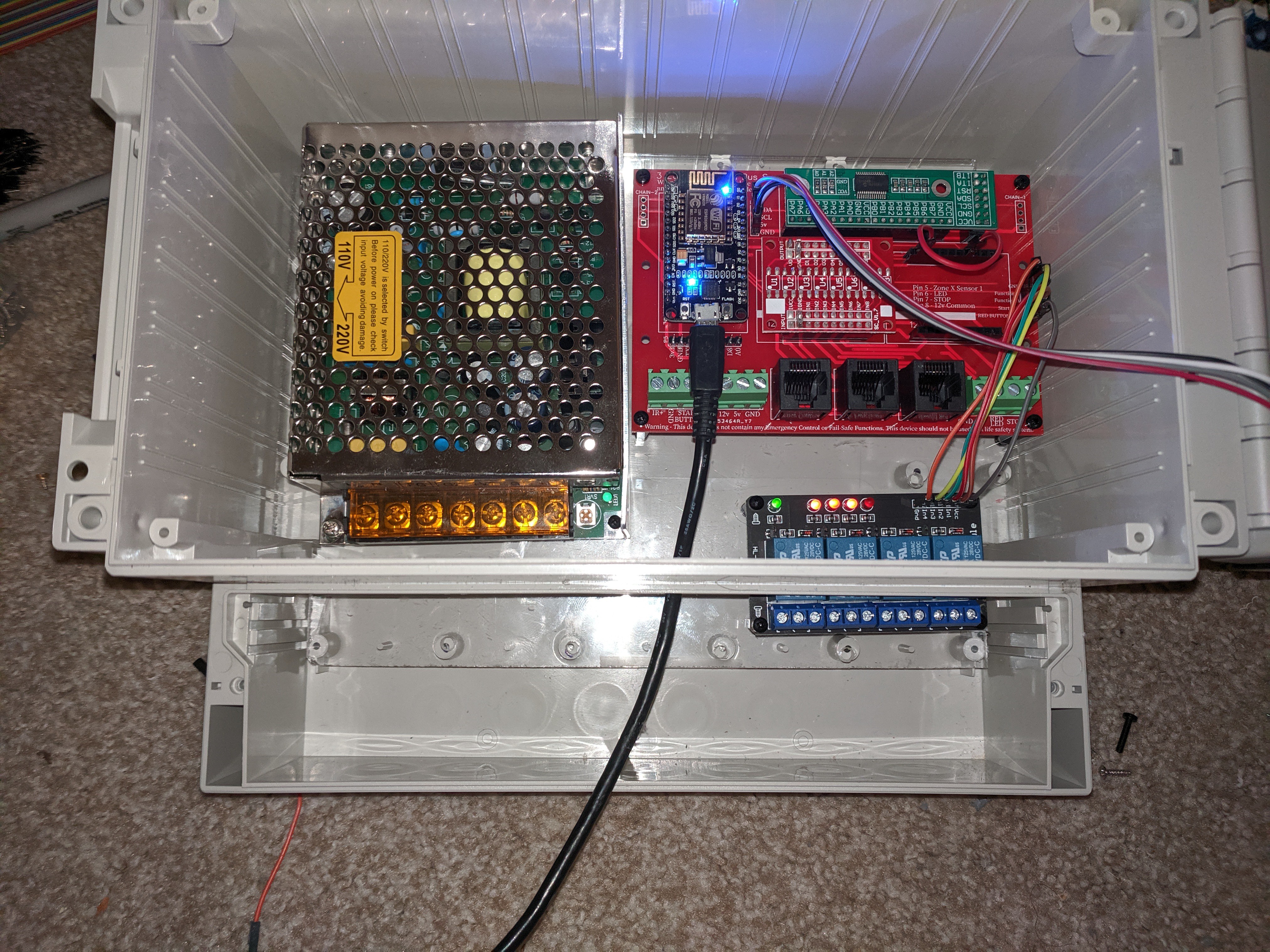
With the logic tested as much as I can in simulation. When I got home I mounted the PCB, power supply, LCD and relay module to the polycarbonate sheet. With the devices inside the enclosure, it is starting to look good. Hopefully tomorrow or the day after I can get the C14 Power plug, Start (Green) button, Stop (Red) button, Config (Blue) button, and USB extender mounted and wired up.
Hotel room programming:
Mounted:
 Jason
Jason
Discussions
Become a Hackaday.io Member
Create an account to leave a comment. Already have an account? Log In.