My MODUS implementation on the STM8 eForth platform works. It was the RS485 communication that left me frustrated for a couple of months.
Since recently "designed" a small PCB to bring SO8 STM8S001J3M3 to good use, and now RS485 testing should better work.
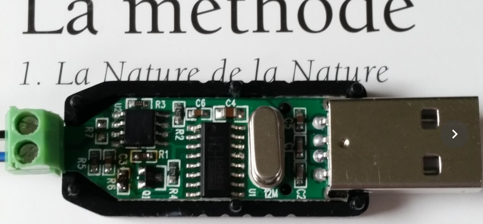
The problem is that the one USB to RS485 adapter that I own, a Green+Black $0.80 gadget, doesn't play nice with my Ubuntu PC. In fact, it's able to receive things but transmitting leads nowhere. Besides, it makes as well Picocom, e4thcom and my JAMOD test hang on exit.
The PCB of the board has YYH-256 stamped on the back. The circuit appears to be simple enough:

It's based on a CH340G, the venerable Chinese USB RS232 interface chip. Has a full set of hardware handshake signals that potentially could be used for switching between Rx and Tx mode. Potentially, because there is no documentation whatsoever.
I first started playing with Picocom DTR toggling but stopped doing that (and felt a bit silly) when I remembered the Linux kernel USB-serial non-features.
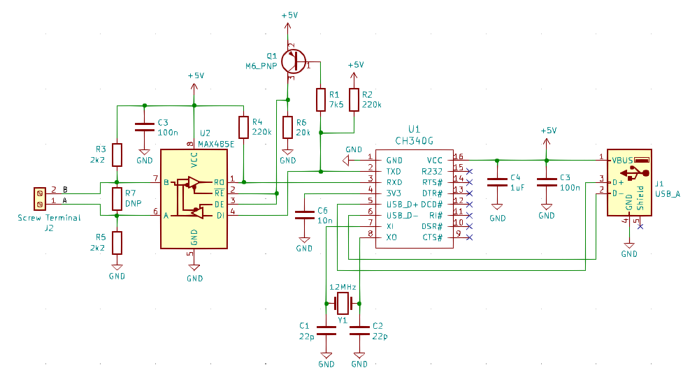
Next I started to think how cool it would be to have a circuit diagram of that simple thing. I fired up KiCad, and with the help of my trusty multimeter, I came up with this:

There is no DTR, no RTS, and thus no elaborate RS232 hardware handshake. Instead I find a *really optimistic* Tx based direction control. I would at least have expected a capacitor to prevent direction switching during transmission of a single character (!). No wonder that RS485-A is biased GND and RS485-B to 5V: the RS485 driver is only driving one polarity! The other one is just the 2.2k resistors doing their work (good luck with the promised 1 km) Is this how the CAN bus was invented?
I don't mean to say that such a circuit won't work under certain circumstances, but mine never did.
The next attempt was checking TxD for signs of life (pin2 of the CH340G), but again nothing.
A quick comparison of the circuit with a CH340G based standard USB-to-TTL adapter didn't reveal any difference: the inputs, besides RxD are N.C. as well (besides, I figured out why the same USB-to-TTL board never worked with the STM8 eForth two-wire-interface - some docs will have to be changed).
There can be just one conclusion: the CH340G on the RS485 Black+Green adapter must be broken.
EDIT: Today a new "RS485 Green and Black" dongle for $0.82 (including postage!) arrived. It worked as expected, but of course because of the design it's only usable for testing or configuring a device on the bench.
 Thomas
Discussions
Become a Hackaday.io Member
Create an account to leave a comment. Already have an account? Log In.
Hi,
im using MAX3140CEI+ for RS485 in half duplex and an exact USB dongle you have, In my Design of MAX3140CE+ the A diff pin is pulled to 5V and B is pulled to gnd, in the schematic you have shown its the opposite, when i connected its not working.
Also can you tell me in detail how pulling up in such fashion will work, because i thought A should be pulled high and B pulled down to ground. And there is 120ohm termination resistor missing there too.
Are you sure? yes | no
The design above is there as a warning, not as an advice, and I wouldn't recommend to copy it. I might also have made an error in my efforts to reverse engineering that very cheap dongle.
I made a CH340E based design that works well: https://github.com/TG9541/rs485-ch340e
Are you sure? yes | no