Two PCB's are designed now:
- The CPU
- A mainboard for the CPU
The video part is not designed yet. The mainboard has a 96 pin connector (same as CPU) where the video PCB can be placed once it is ready.
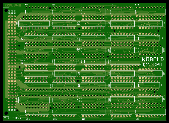
Here comes the CPU impression from the PCB makers website:
And the mainboard:
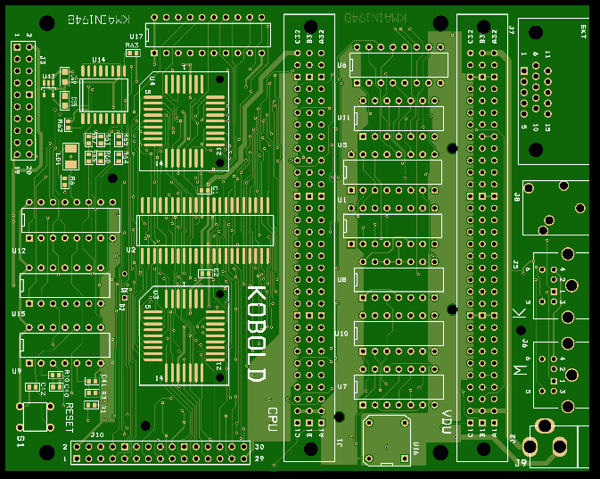
The mainboard has:
- DIN41612 connector for CPU
- DIN41612 connector for Video card
- Two 8-bit wide PLCC Flash ROMs
- 256K x 16 SRAM
- 32 MByte serial SPI flash
- clock circuits
- address decoding
- some I/O
- connector for Raspberry Pi for Flash programming and debugging
- A software controllable LED
- I/O connectors
Schematics of CPU and mainboard are in the file section.
Let the waiting begin.....
In the mean time, I have time to order some parts.
Discussions
Become a Hackaday.io Member
Create an account to leave a comment. Already have an account? Log In.