This 16 bit processor has a 20 bit address bus. How is this address generated ?
Around 40 years ago, developers of the Intel 8086 were facing the same problem. This time, we will use an easier solution. But I doubt if my solution will be more successful.
In the Kobold K2, memory can be accessed with the following addressing modes:
ADDRESS REGISTER INDIRECT
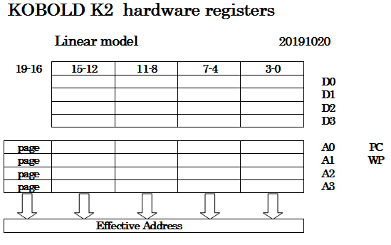
Each of the four address registers has its own 4-bit page register. A page register can be written with a MOVP instruction.
The memory address consists of bit 0-15 coming from the address register and bit 16-19 coming from the corresponding page register.
In instructions that use this mode, the displacement should be set to zero.
INDIRECT WITH DISPLACEMENT
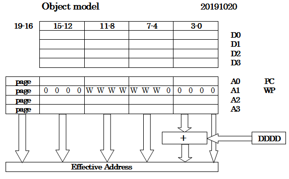
This is considered the main addressing mode. In this mode, the 4-bit displacement value in the instruction is added to bit 1 - 4 of the address. There is no carry from bit 4 to higher bits.
In C terms, the address register can contain a pointer to many different structure instances. Each structure has a maximum of 16 word-sized members. The instruction can specify which member is addressed. This supports the "->" operator in a single instruction.
Register A1 is intended to be used as 'workspace pointer', pointing to a set of 16 locations that can be used as local variables in a function. When a function is called, the workspace pointer can be set to a new value to get a fresh set of variables, so it is not needed to push the old ones on a stack one by one.
As you can see in the picture, there can be seven W bits to define the workspace so 128 sets of registers are available.
ZERO PAGE ADDRESSING
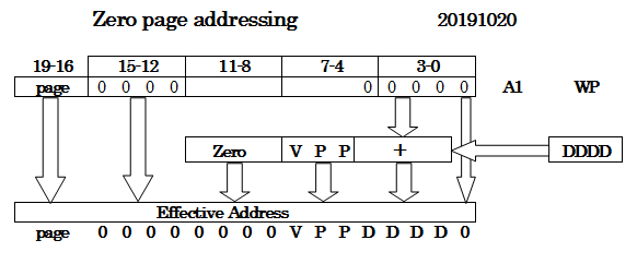
There is also absolute addressing. Only short addresses, that are a part of the 16-bit instruction, are supported. It is called Zero page addressing because the upper part of the address is always zero. The instruction delivers the bits VPPDDDD, for a range of 128 locations. Note that this mode also uses the value of several workspace pointer bits.
WORD OR BYTE ACCESS
The K2 is designed as a 16 bit processor that reads or writes 16 bits from/to memory at the same time.
In order not to exclude languages like C, support for 8-bit characters was added. Therefore, the K2 can address bytes or words in memory. The address in bit 0-15 is a byte address, so for accessing words, addressbit A0 is always zero.
For 8-bit instructions that read or write memory, the lowest address bit determines if the low or high byte in memory is used. The K2 is little-endian.
However, to keep component count reasonable, a little software effort will be needed to read or write bytes:
- When reading a byte, the low byte will always be the requested byte, but the high byte will in most cases not be zero. To be more precise, for memory-read actions there is no difference for byte- or word instructions. When A0=0, reading the low byte is done in exactly the same way as reading a word. when A0=1, the high byte is copied to the low byte but the high byte is not set to zero. So it might be needed to AND the result with 0x00FF. Since there is no AND instruction, read it into a data register with MOVC (move complement) and then do NOR 0xFF00 to get the same result.
- There is a special MOVB instruction to write a byte to memory. The hardware will write only the low or high byte, depending on A0. But when writing, a word should be written with the high byte being equal to the low byte. This could be done with a simple look-up table with 256 locations.
Note that the processor registers will always contain words.
Discussions
Become a Hackaday.io Member
Create an account to leave a comment. Already have an account? Log In.
i love the level of documentation you are doing on this build! keep it going!
Are you sure? yes | no
Thanks Dave ! BTW how is your WITCH replication doing ?
Are you sure? yes | no