0%
0%
My Very Own Geiger Counter
Fulfilling a childhood dream
 Jon Kunkee
Become a Hackaday.io member
Already have an account? Log in.
Just one more thing
To make the experience fit your profile, pick a username and tell us what interests you.
Pick an awesome username
hackaday.io/
Your profile's URL: hackaday.io/username. Max 25 alphanumeric characters.
Pick a few interests
Projects that share your interests
People that share your interests

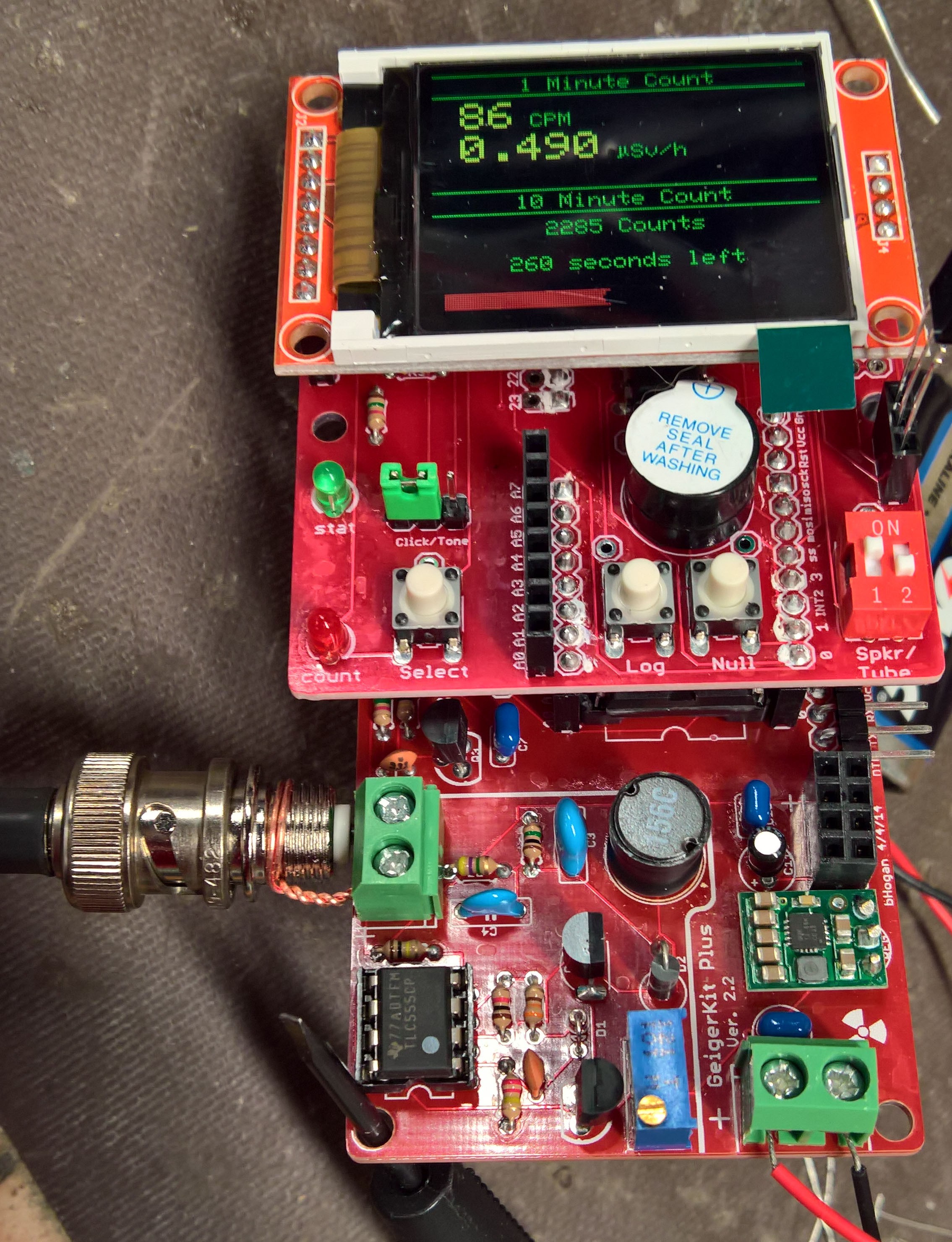
 Here's the whole assembly.


 Colin Catlin
 KingOfKYA(Travis K. )
 Chris
Chris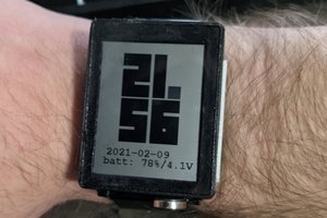
 Jeff Cooper
Yeah, same here. I somehow found a "Build Your Own Laser" book and tried so hard to squeeze the money for a He-Ne tube out of my parents. But this was the late 70s, and there was no way it was going to happen. Too young to work, no way to get money, and the idea eventually fell to the wayside.