PCB received, components soldered, boards plugged, debug begins:
Sometimes the debug part of a project can be very time consuming sometime it doesn't. :-)
After a quick check everything is working, the longest part was to download a RPI image and flash it on a SDCard.
Let's look at the block diagram :
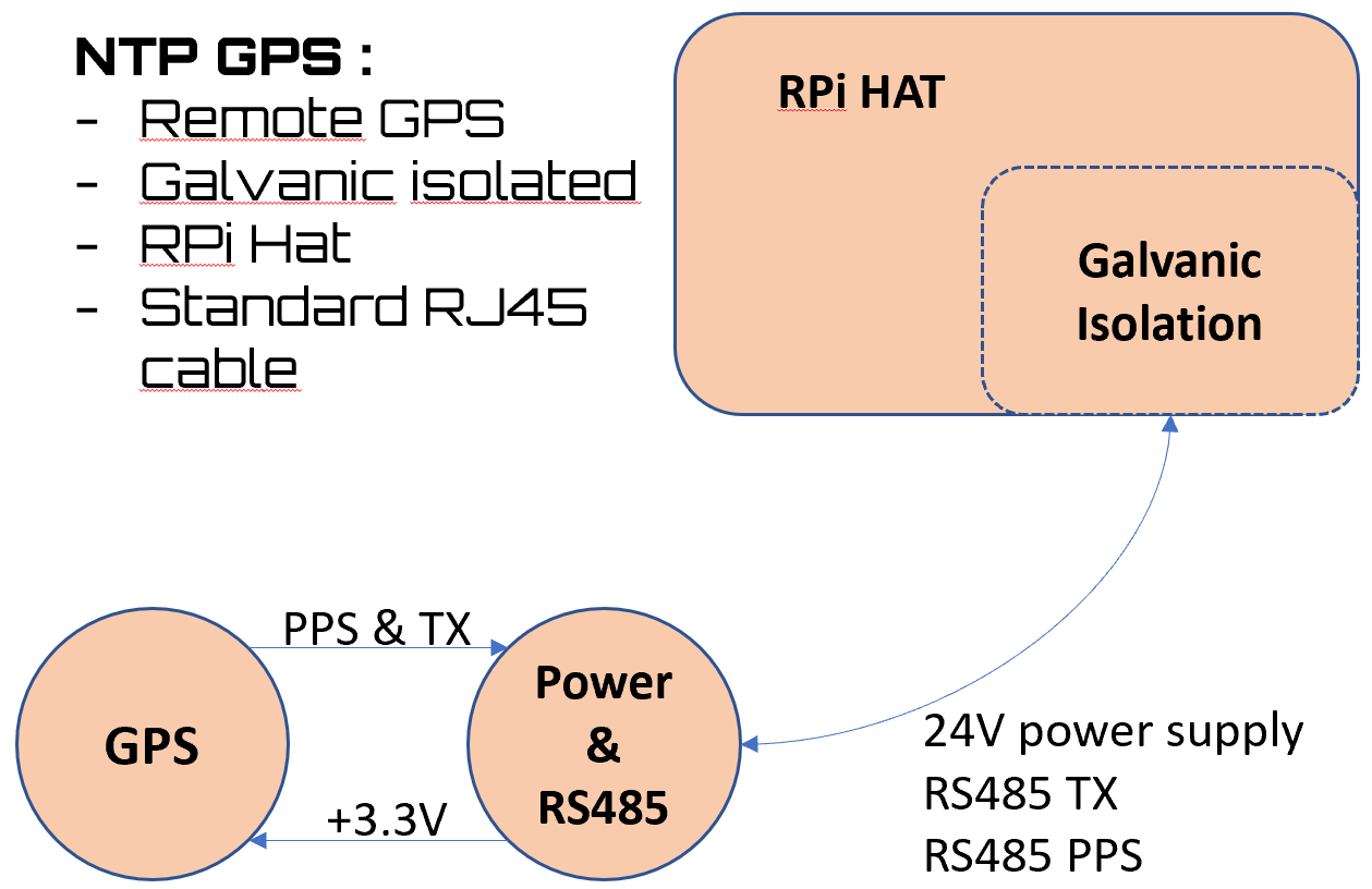
The GPS head is powered by a 24V rail coming from the RPI Hat, the PPS output and TX serial are converted to RS485 for long range communication.
The 24V rail is converted to 5V through a DC/DC buck converter to power the RS485 transmitters, and a 3.3V LDO is used to power the GPS module :
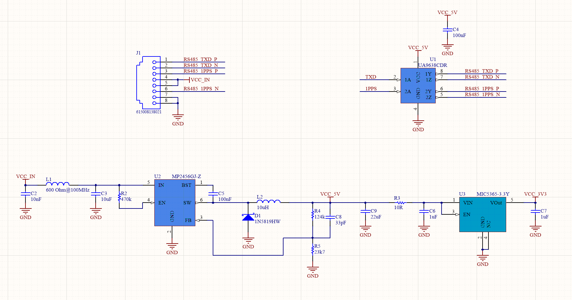
A small micro controller was put on the board to configure the GPS module but the default configuration is working great so this micro controller is not used.
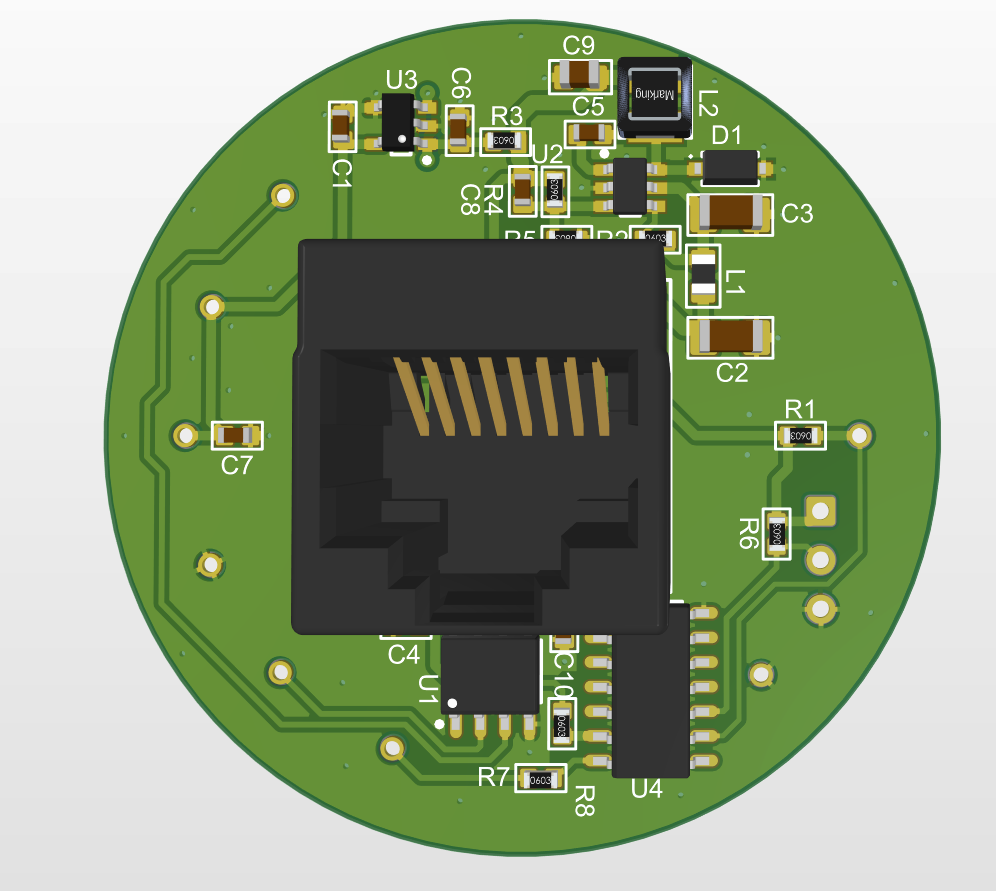
The use of a RJ45 connector allows a simple Ethernet cable to connect the GPS Head to the RPI Hat.
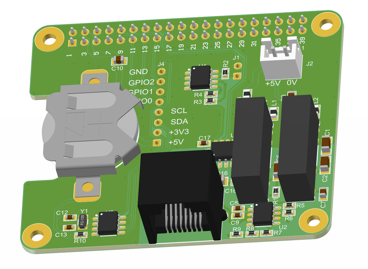
The RPI Hat consists mainly in a dual RS485 receiver and galvanic isolation to power the GPS head.
The circuit for RS485 receivers is as follow :
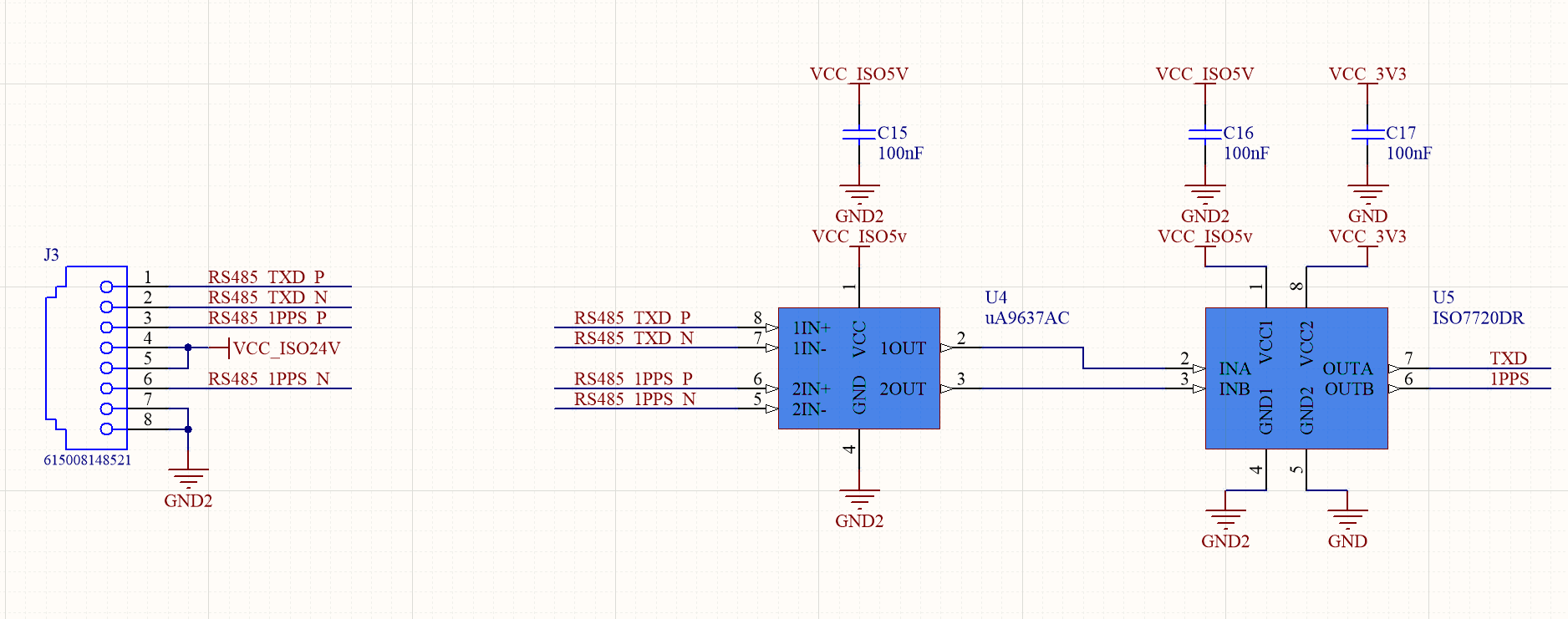
The UA9637 converts the RS485 signals in TTL 5V and the digital isolator ISO7720DR drives the input of the RPi at 3.3V.
Termination resistors should be added, I unfortunately forgot them on the schematic but they can easily be soldered directly on the SO8 pins of U4.
Two isolated DC/DC module provide the 24V for the GPS head and a local isolated 5V for the RS485 receiver.
After plugin everything together, the GPS is sending data to the RPI on serial port and a very stable 1PPS pulse is driving GPIO23 on the 40 pin connector.
Success for the hardware part. In a next update we'll look at the software on RPi to set up a NTP server.
Discussions
Become a Hackaday.io Member
Create an account to leave a comment. Already have an account? Log In.