 land-boards.com
Serial I/O Emulation
Normally, serial I/O using the 6850, SIO or DART consists of two I/O mapped locations per serial port. One I/O address is for data read/write. The other I/O address is for status/control. In the case of the 6850 UART this reduces down to just two bits of status (Transmitter full and Receiver empty) and the 8-bit data read/write register.
Polled Serial I/O
Serial output from Z80 works by the Z80 polling the Transmit not full register waiting for transmit not full and then writing the data to transmit in the Transmit Output buffer. This action is emulated by the PSoC. The Z80 requests the status register value which the PSoC presents. The PSoC determines the value that should be sent to the status register by looking at it's own UART interface. If the PSoC UART transmitter is not full then it returns that status to the Z80. The Z80 sees that the transmitter is not full and then sends out the transmit byte. The PSoC picks up the transmit byte and puts it out to the UART.
Read operations are similar. The Z80 reads the UART status register which is emulated by the PSoC and waits for receive data to be present. It then requests the data by performing a read which causes the PSoC to read the UART and return the value to the Z80.
From the PSoC Perspective
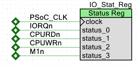
From the PSoC operations consist of either waiting for an interrupt or polling the IO_Stat_Reg and waiting for IORQ* to go active.
When IORQ* goes active the PSoC then takes the values in the IO_Stat_Reg status register to determine the operation. It also takes the address from the AdrLowIn status register to determine the peripheral address that is being accessed by the Z80.
Interrupt Driven I/O
Interrupt driven I/O is only a bit more complicated. The PSoC generates the INT* line to the Z80 indicating that an interrupt is present. This causes the Z80 to issue the following timing:
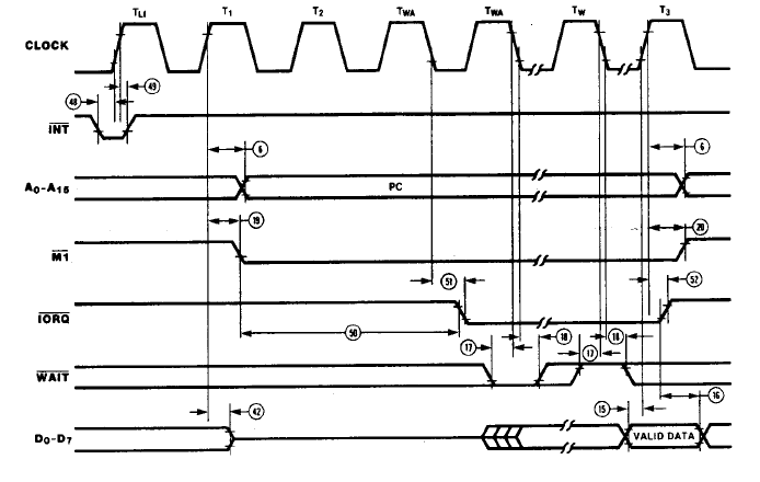
In response, the PSoC places the interrupt vector onto the data bus to the Z80. This operation by the Z80 is similar to an I/O read with the exception that the M1* line is active (low) during the read of the interrupt vector. The PSoC sees the M1* line low and knows that this an I/O operation reading an interrupt vector.
This behavior can be emulated by the PSoC by monitoring the M1* line.
The PSoC sees the M1* line low and knows that this an I/O operation reading an interrupt vector. This seems to be a common source of confusion for many designers who do not include M1* in their logic. If it's a standard Z80 peripheral chip it probably knows to not send out normal data, but send out the interrupt vector.
The interrupt vector could be implemented with some additional logic in the PSoC but would come at the cost of 8 of 2:1 multiplexers on the data bus out of the PSoC to the Z80. With this emulation method there's no real advantage to adding extra logic for this function. If M1* is high then the read is a "normal" I/O read. If the M1* is low then the read is an interrupt vector read. In either case, the PSoC provides the requested value.
The reading of the interrupt vector by the Z80 is the interrupt acknowledge and will remove the interrupt.
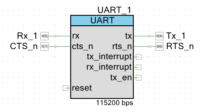
The PSoC hardware to implement the external UART is relatively straightforward.
The Configuration for the UART is:
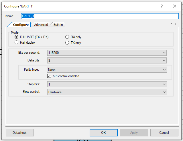
This configuration allows the UART to be software controlled (for baud rate and other configuration values). It also provides hardware handshake lines. The PSoC UART can be set up to interrupt on various conditions.
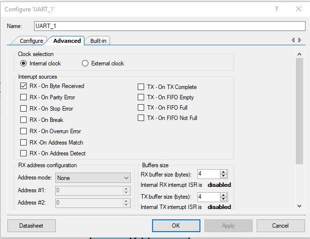
These can be used to mimic the interrupt characteristics of the Serial I/O being emulated.
Sequence of Operations - Serial In - Polled
The steps to receive data from the serial port are:
- Z80 issues a read request to the UART Status register address
- PSoC receives the read request either by polling the IO_Stat_Reg or by receiving an interrupt via IO_Op_Int
- PSoC reads the I/O address from the Z80 - by reading AdrLowIn status register
- PSoC classifies the transfer as a normal read of I/O at the status address loaded from AdrLowIn
- PSoC figures out the receive status by checking the receive character status by calling the function auto-generated by the PSoC Creator (essentially an application builder) called UART_1_ReadRxStatus( )
- PSoC similarly figures out the transmit status by calling UART_1_ReadTxStatus( )
- The PSoC packs the responses into a return value and puts the value into the output mailbox Z80_Data_In
- The PSoC indicates to the Z80 that the status data has been read by pulsing CLR_IO_INT
- The Z80 repeats these above steps until there is a receive character
- The PSoC doesn't know why the Z80 is requesting status (it could be for a transmit or receive) so it needs to pack all of the bits into the status everytime
- After the Z80 sees that the data is present, it sends the Serial IO data register address to the PSoC
- The PSoC reads its UART and returns the data (as above for status)
Sequence of Operations - Serial Out - Polled
This is very similar to the above example for reads. The difference is the transmit bits are used.
This all seems complicated but it's really not all that complicated. Basically, the function of the I/O interface of any Z80 peripheral can be emulated by the PSoC. This consists of emulating the internal registers of the peripheral and connecting them to the peripheral functions in the PSoC. The UART example above is familiar. Others may be less familiar. Some, like timers may require additional sofware/hardware in the PSoC to emulate the function of the chip.
The beauty of this design method is that the peripherals can be switched in/out of the design by creating a bit of code to emulate their control/status interface and the PSoC can do all of the work.
Discussions
Become a Hackaday.io Member
Create an account to leave a comment. Already have an account? Log In.