 land-boards.com
I'm going to create a stand-alone PSoC project to use the PSoC to read SD cards. I'm going to start with the hardware defines for this project (which should leave the Z80 hardware pins unmolested) and just not download code.
For the software piece, I will add parts of the code I created to test the I2C EEPROM on our Not Quite Useless Raspberry Pi. This log entry covers that function. The code for that project reads the EEPROM on a Raspberry Pi hat and dumps it to the USB-Serial port for display on the PC in a serial terminal (PuTTY). The portion of that code that I want to copy is the dump of a PSoC memory buffer to the serial port as well as a bit of the command processor.
The goal is to dump the contents of the SD card in 512-byte sectors at a time to the USB-Serial and view it with PuTTY. We should also be able to view the SD card contents with HxD (described in a previous log post) and see that we got the right data.
It is tempting to do a straight port of the example code from the previous example which writes a byte at a time to the SPI interface and manually controls the Slave Select line. The I2C bus has support for reading data into a buffer or writing a buffer worth of data out automatically.
The Cypress datasheet for the SPI master lists the API functions that the PSOC Creator supports. In fact, PSOC Creator auto-generates these API so there's no effort required to create them. There is some support for putting an array of data into the transmit buffer - the function is SPIM_PutArray( ). There is also a PSOC 6 design example in the MCU SPI Master for performing SPI using Low-Level DMA but the symbol doesn't have rx_dma and tx_dma pins in the PSOC Creator for PSOC 5 parts.
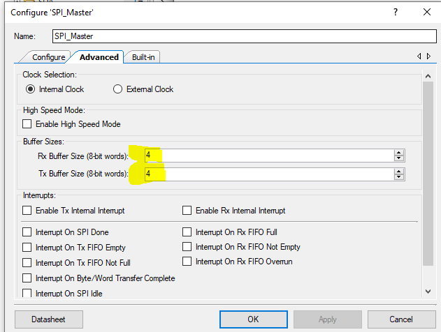
It is worth noting that there are Rx and Tx Buffers built into the SPI master. The default depth is 4 bytes for each. This should be enough to have gap-less data transmit and receive.
 The interface could also be interrupt driven but I don't see it as a problem if the Z80 ends up waiting on the SD card. The 512 byte block from the SD card can be read by the PSoC into a receive block. The Z80 is waiting around for data anyway. The entire block can be read into PSoC memory and then the status returned to the Z80 that there is data present.
The same applies to the 512 byte block writes to the SD card. The write could return control control to the Z80 as soon as it is written and the Z80 could go about it's business while the block finishes the write.
All of this means that transfers to/from the SD card will be done through 512-byte buffers in the PSoC internal RAM. Writes from the Z80 will be to the transmit block and after the last byte is written from the Z80, the block will be transferred to the SD card. Reads from the Z80 will wait on the block to be completely read before returning status to the Z80 that receive data from the SD card is ready.
To begin with we only have to support reads so we will ignore SD card writes for the first cut.
PSoC Monitor Program
Up to this point the PSoC just runs the code to communicate with the Z80. For these next steps let's add a monitor program to run in place of the Z80 control. But how can we invoke the monitor program and not run the Z80 Peripheral Emulation? After all, we will want control of the USB-Serial interface and it's currently owned by the SIO/M6850 emulator when the Z80 is used.
The upper left button on the Front Panel exits the Front Panel code without releasing the reset to the Z80. We will use this feature to run monitor code that leaves the Z80 in reset and lets us test the SD card interface. To make use of this we will add a return value to the runFrontPanel( ) function. The return value will indicate to main( ) that we exited the Front Panel function without releasing reset.
Then we replicate the forever current loop in main( ) with a loop that handles the USB-Serial and runs a simple command driven menu. Fortunately, I created this code recently for our Not Quite Useless Raspberry Pi. Changing the code to not read EEPROM but instead read the SD card gets us what we want.
Here's a dummy block as read by the new PSoC Monitor Program:
Read from the SD Card
0000  00 01 02 03 04 05 06 07 08 09 0a 0b 0c 0d 0e 0f  ................
0010  10 11 12 13 14 15 16 17 18 19 1a 1b 1c 1d 1e 1f  ................
0020  20 21 22 23 24 25 26 27 28 29 2a 2b 2c 2d 2e 2f  .!"#$%&'()*+,-./
0030  30 31 32 33 34 35 36 37 38 39 3a 3b 3c 3d 3e 3f  0123456789:;<=>?
0040  40 41 42 43 44 45 46 47 48 49 4a 4b 4c 4d 4e 4f  @ABCDEFGHIJKLMNO
0050  50 51 52 53 54 55 56 57 58 59 5a 5b 5c 5d 5e 5f  PQRSTUVWXYZ[\]^_
0060  60 61 62 63 64 65 66 67 68 69 6a 6b 6c 6d 6e 6f  `abcdefghijklmno
0070  70 71 72 73 74 75 76 77 78 79 7a 7b 7c 7d 7e 7f  pqrstuvwxyz{|}~.
0080  80 81 82 83 84 85 86 87 88 89 8a 8b 8c 8d 8e 8f  ................
0090  90 91 92 93 94 95 96 97 98 99 9a 9b 9c 9d 9e 9f  ................
00a0  a0 a1 a2 a3 a4 a5 a6 a7 a8 a9 aa ab ac ad ae af  ................
00b0  b0 b1 b2 b3 b4 b5 b6 b7 b8 b9 ba bb bc bd be bf  ................
00c0  c0 c1 c2 c3 c4 c5 c6 c7 c8 c9 ca cb cc cd ce cf  ................
00d0  d0 d1 d2 d3 d4 d5 d6 d7 d8 d9 da db dc dd de df  ................
00e0  e0 e1 e2 e3 e4 e5 e6 e7 e8 e9 ea eb ec ed ee ef  ................
00f0  f0 f1 f2 f3 f4 f5 f6 f7 f8 f9 fa fb fc fd fe ff  ................
0100  00 01 02 03 04 05 06 07 08 09 0a 0b 0c 0d 0e 0f  ................
0110  10 11 12 13 14 15 16 17 18 19 1a 1b 1c 1d 1e 1f  ................
0120  20 21 22 23 24 25 26 27 28 29 2a 2b 2c 2d 2e 2f  .!"#$%&'()*+,-./
0130  30 31 32 33 34 35 36 37 38 39 3a 3b 3c 3d 3e 3f  0123456789:;<=>?
0140  40 41 42 43 44 45 46 47 48 49 4a 4b 4c 4d 4e 4f  @ABCDEFGHIJKLMNO
0150  50 51 52 53 54 55 56 57 58 59 5a 5b 5c 5d 5e 5f  PQRSTUVWXYZ[\]^_
0160  60 61 62 63 64 65 66 67 68 69 6a 6b 6c 6d 6e 6f  `abcdefghijklmno
0170  70 71 72 73 74 75 76 77 78 79 7a 7b 7c 7d 7e 7f  pqrstuvwxyz{|}~.
0180  80 81 82 83 84 85 86 87 88 89 8a 8b 8c 8d 8e 8f  ................
0190  90 91 92 93 94 95 96 97 98 99 9a 9b 9c 9d 9e 9f  ................
01a0  a0 a1 a2 a3 a4 a5 a6 a7 a8 a9 aa ab ac ad ae af  ................
01b0  b0 b1 b2 b3 b4 b5 b6 b7 b8 b9 ba bb bc bd be bf  ................
01c0  c0 c1 c2 c3 c4 c5 c6 c7 c8 c9 ca cb cc cd ce cf  ................
01d0  d0 d1 d2 d3 d4 d5 d6 d7 d8 d9 da db dc dd de df  ................
01e0  e0 e1 e2 e3 e4 e5 e6 e7 e8 e9 ea eb ec ed ee ef  ................
01f0  f0 f1 f2 f3 f4 f5 f6 f7 f8 f9 fa fb fc fd fe ff  ................
his code dumps a 512-byte block which is filled with dummy values. These dummy values will be replaced by the real data from from the SD Card. The block is read by pressing "R" on the PuTTY terminal.
Block Read Command
Here's a Logic Analyzer capture of the initialization pulses.
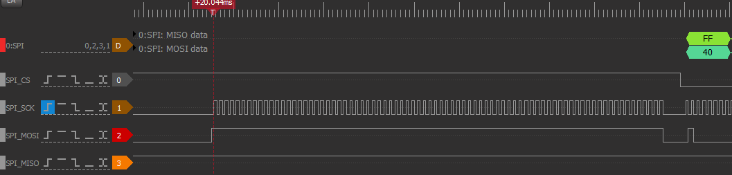
Here's the 0x40 command.
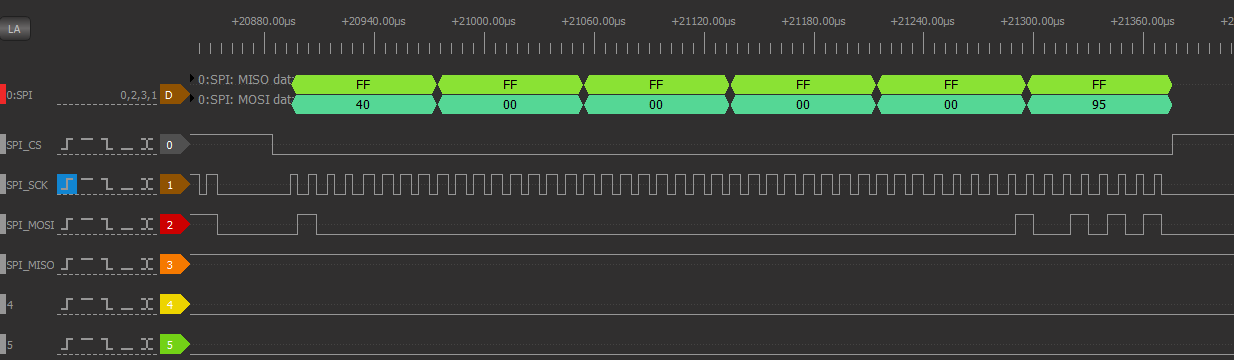
Here's the status polling sequence.
The 0x01 shows up in the sequence which confirms the card status is ready.
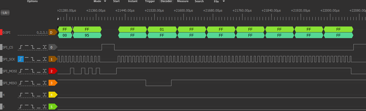
Here's the 0x40, 0x41 and 0x50 sequence along with the card responses.
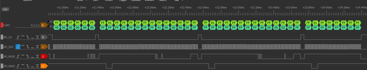
That is the initialization sequence for the card. The 0x1 status values show that the card is responding. The Bus Pirate version of the read sector command is:
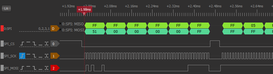
Read sector: [0x51 0x00 0x00 0x00 0x00 0xFF r:520]
The read sector command is the same as the above commands except it reads back 512 bytes.
The example code from the tutorial has the following C code:
void SD_read(unsigned long sector, unsigned short offset, unsigned char * buffer, unsigned short len) {
    unsigned short i, pos = 0;

    CS_ENABLE();
    SPI_write(0x51);
    SPI_write(sector>>15); // sector*512 >> 24
    SPI_write(sector>>7);  // sector*512 >> 16
    SPI_write(sector<<1);  // sector*512 >> 8
    SPI_write(0);          // sector*512
    SPI_write(0xFF);

    for(i=0; i<100 && SPI_write(0xFF) != 0x00; i++) {} // wait for 0

    for(i=0; i<100 && SPI_write(0xFF) != 0xFE; i++) {} // wait for data start

    for(i=0; i<offset; i++) // "skip" bytes
        SPI_write(0xFF);

    for(i=0; i<len; i++) // read len bytes
        buffer[i] = SPI_write(0xFF);

    for(i+=offset; i<512; i++) // "skip" again
        SPI_write(0xFF);

    // skip checksum
    SPI_write(0xFF);
    SPI_write(0xFF);

    CS_DISABLE();
}
My code is similar but doesn't slice up the data into a small buffer.
    ///////////////////////////////////////////////////////////////////////////////
    // void SD_readSector(uint32 sector, uint8 * buffPtr)

    void SD_readSector(uint32 sector, uint8 * buffPtr)
    {
        uint16 loopCount = 0;
        uint8 junk;
        SPI_write(0x51);
        SPI_write(sector>>15);
        SPI_write(sector>>7);
        SPI_write(sector<<1);
        SPI_write(0);
        SPI_write(0xFF);
        while((SPI_Master_ReadTxStatus() & SPI_Master_TX_FIFO_CLR) != SPI_Master_TX_FIFO_CLR);
        CyDelayUs(20);
        // wait for 0
        for(loopCount=0; loopCount<100; loopCount++)
        {
            SPI_write(0xFF);
            while ((SPI_Master_ReadRxStatus() & SPI_Master_RX_FIFO_CLR) == SPI_Master_RX_FIFO_CLR);
            if (SPI_Master_ReadRxData() == 0)
                break;
        }
        // wait for 0xFE
        for(loopCount=0; loopCount<100; loopCount++)
        {
            SPI_write(0xFF);
            while ((SPI_Master_ReadRxStatus() & SPI_Master_RX_FIFO_CLR) == SPI_Master_RX_FIFO_CLR);
            if (SPI_Master_ReadRxData() == 0xFE)
                break;
        }
        for(loopCount=0; loopCount<512; loopCount++)
        {
            SPI_write(0xFF);
            while ((SPI_Master_ReadRxStatus() & SPI_Master_RX_FIFO_CLR) == SPI_Master_RX_FIFO_CLR);
            buffPtr[loopCount] = SPI_Master_ReadRxData();
        }

        SPI_write(0xFF);
        while ((SPI_Master_ReadRxStatus() & SPI_Master_RX_FIFO_CLR) == SPI_Master_RX_FIFO_CLR);
        junk = SPI_Master_ReadRxData();

        SPI_write(0xFF);
        while ((SPI_Master_ReadRxStatus() & SPI_Master_RX_FIFO_CLR) == SPI_Master_RX_FIFO_CLR);
        junk = SPI_Master_ReadRxData();

        return;
    }
My SD card is returning a "bad" status. Rather than 0x00, it is returning 0x05.
So near, and yet so far.
Slept on It
Slept for a while and decided to check the SD_init( ) code from the fat88.c code. It's got delays between commands. The bus pirate manual commands would have had time delays due to entering the commands by hand. The code has:
char SD_init() {
	char i;

	// ]r:10
	CS_DISABLE();
	for(i=0; i<10; i++) // idle for 1 bytes / 80 clocks
		SPI_write(0xFF);

	// [0x40 0x00 0x00 0x00 0x00 0x95 r:8] until we get "1"
	for(i=0; i<10 && SD_command(0x40, 0x00000000, 0x95, 8) != 1; i++)
		_delay_ms(100);

	if(i == 10) // card did not respond to initialization
		return -1;

	// CMD1 until card comes out of idle, but maximum of 10 times
	for(i=0; i<10 && SD_command(0x41, 0x00000000, 0xFF, 8) != 0; i++)
		_delay_ms(100);

	if(i == 10) // card did not come out of idle
		return -2;

	// SET_BLOCKLEN to 512
	SD_command(0x50, 0x00000200, 0xFF, 8);

	sd_sector = sd_pos = 0;

	return 0;
}
Changed my SD_init( ) code to match:
    void SDInit(void)
    {
        uint8 iter;
        // Dummy fill the read/write buffers
        for (uint16 loopCount=0; loopCount<512; loopCount++)
        {
            readSDBuffer[loopCount] = (uint8)loopCount;
            writeSDBuffer[loopCount] = ~(uint8)loopCount;
        }

        // p 5 of http://www.dejazzer.com/ee379/lecture_notes/lec12_sd_card.pdf
        //
        // https://codeandlife.com/2012/04/25/simple-fat-and-sd-tutorial-part-3/
        // Init and go to SPI mode: ]r:10 [0x40 0x00 0x00 0x00 0x00 0x95 r:8]

        // Send at least 74 clocks with SS and MOSI high
        SPI_SS_Override_Write(1);                   // Force SPI_SS line high
        SPI_Master_Start();
        for (uint8 loopCount = 0; loopCount < 10; loopCount++)
        {
            while ((SPI_Master_ReadTxStatus() & SPI_Master_STS_TX_FIFO_NOT_FULL) == 0);
            SPI_Master_WriteTxData(0xff);   // Hang around while the FIFO is full
        }
        // Wait around for the FIFO to get empty
        while((SPI_Master_ReadTxStatus() & SPI_Master_TX_FIFO_CLR) != SPI_Master_TX_FIFO_CLR);
        SPI_SS_Override_Write(0);                   // Allow the SPI_Master to control the SPI_SS line
        CyDelayUs(10);
        SPI_Master_ClearRxBuffer();

        // Initialize card: [0x41 0x00 0x00 0x00 0x00 0xFF r:8]
    	for(iter=0; iter<10 && SD_command(0x40, 0x00000000, 0x95, 8) != 1; iter++)
    		CyDelay(100);

        // Set transfer size: [0x50 0x00 0x00 0x02 0x00 0xFF r:8]
    	for(iter=0; iter<10 && SD_command(0x41, 0x00000000, 0xFF, 8) != 0; iter++)
    		CyDelay(100);

        // Read sector: [0x51 0x00 0x00 0x00 0x00 0xFF r:520]
        SD_command(0x50, 0x00000200, 0xFF, 8);

        // Initialize the Z80 interface
        SD_DataOut = 0x0;
        SD_DataIn = 0x0;
        SD_Status = 0x0;
        SD_Command = 0x0;
        SD_LBA0_Val = 0x0;
        SD_LBA1_Val = 0x0;
        SD_LBA2_Val = 0x0;
        SD_LBA3_Val = 0x0;
    }
And it worked. Here's the dump of the start of the first sector of the SD card.
Land Boards, LLC - Z80_PSoC monitor
R - Read SD Card
? - Print this menu
Read from the SD Card
0000  c3 5c d3 c3 58 d3 7f 00 43 6f 70 79 72 69 67 68  .\..X...Copyrigh
0010  74 20 31 39 37 39 20 28 63 29 20 62 79 20 44 69  t.1979.(c).by.Di
0020  67 69 74 61 6c 20 52 65 73 65 61 72 63 68 20 20  gital.Research..
0030  20 20 20 20 00 00 00 00 00 00 00 00 00 00 00 00  ................
That was somewhat painful but made quite a bit easier by the tutorial. Thanks Joonas Pihlajamaa.
Discussions
Become a Hackaday.io Member
Create an account to leave a comment. Already have an account? Log In.