I want to introduce you to the newest member of the family.
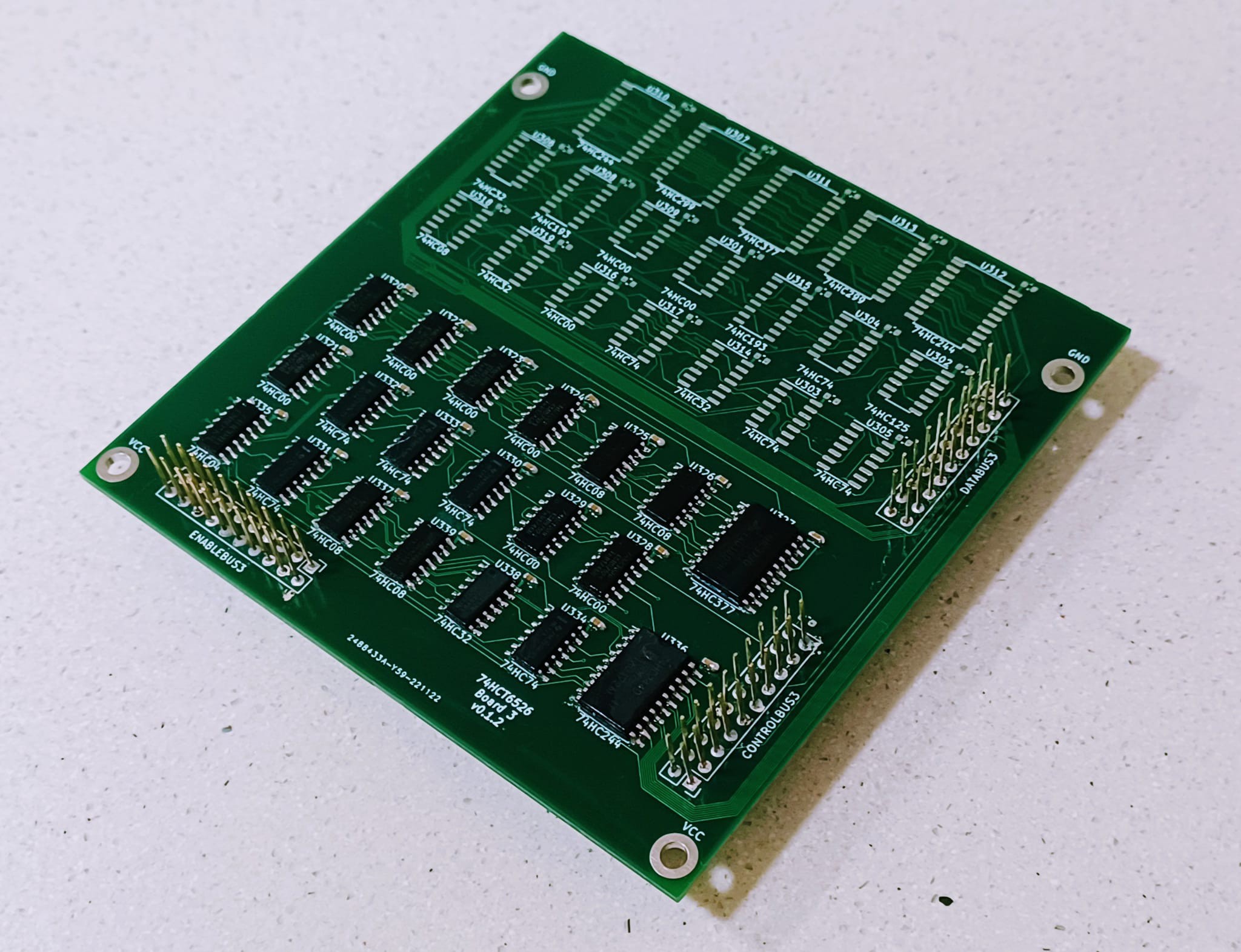
B3, with ICR fully populated. The upper half of the board is the SDR, but I won't be soldering that in until ICR is validated. There are a couple of expensive ICs there (Two 74299 shifters) which I'd rather not to solder until I know the ICR works fine.
And... to my great surprise... it does. I've been only able to do some minor tests, as I finished assembling the ICR just a couple hours ago. So far :
- Interrupt mask can be properly set and cleared.
- Timer A and Timer B interrupts work, and I'm proud to say, the appear cycle exact!
- Flag interrupt it's not working for some reason. Could be a a bad connection or solder joint, as at first glance, I see nothing out of place in the schematic. Further investigation is required.
- TOD and SDR interrupts can't be tested yet, as there's no TOD or SDR to be fire the interrupt. Hope are high, given the circuit for them is pretty much the same as TA and TB
- Timer B bug will require extensive testing. Theres a 50/50 chance of it being "fixed". If I've managed to replicate it, I'm afraid I will also have a Timer A, SDR, TOD, and FLAG interrupt bug.
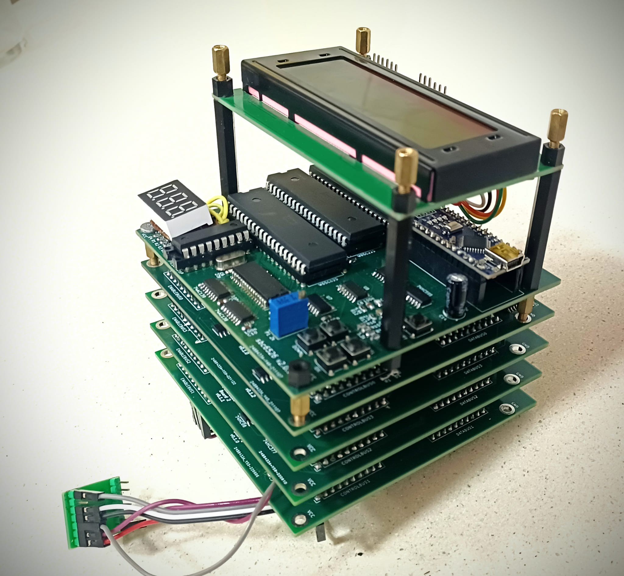
This is truly a huge milestone. I will test as soon as possible the full stack on a real C64, as now I have pretty much everything needed by the computer to work properly. TOD, SDR and Flag interrupts are not used a lot.
Today, after 4 and a half years of work, I'm 99% sure this project will succeed!
Cheers!
Discussions
Become a Hackaday.io Member
Create an account to leave a comment. Already have an account? Log In.