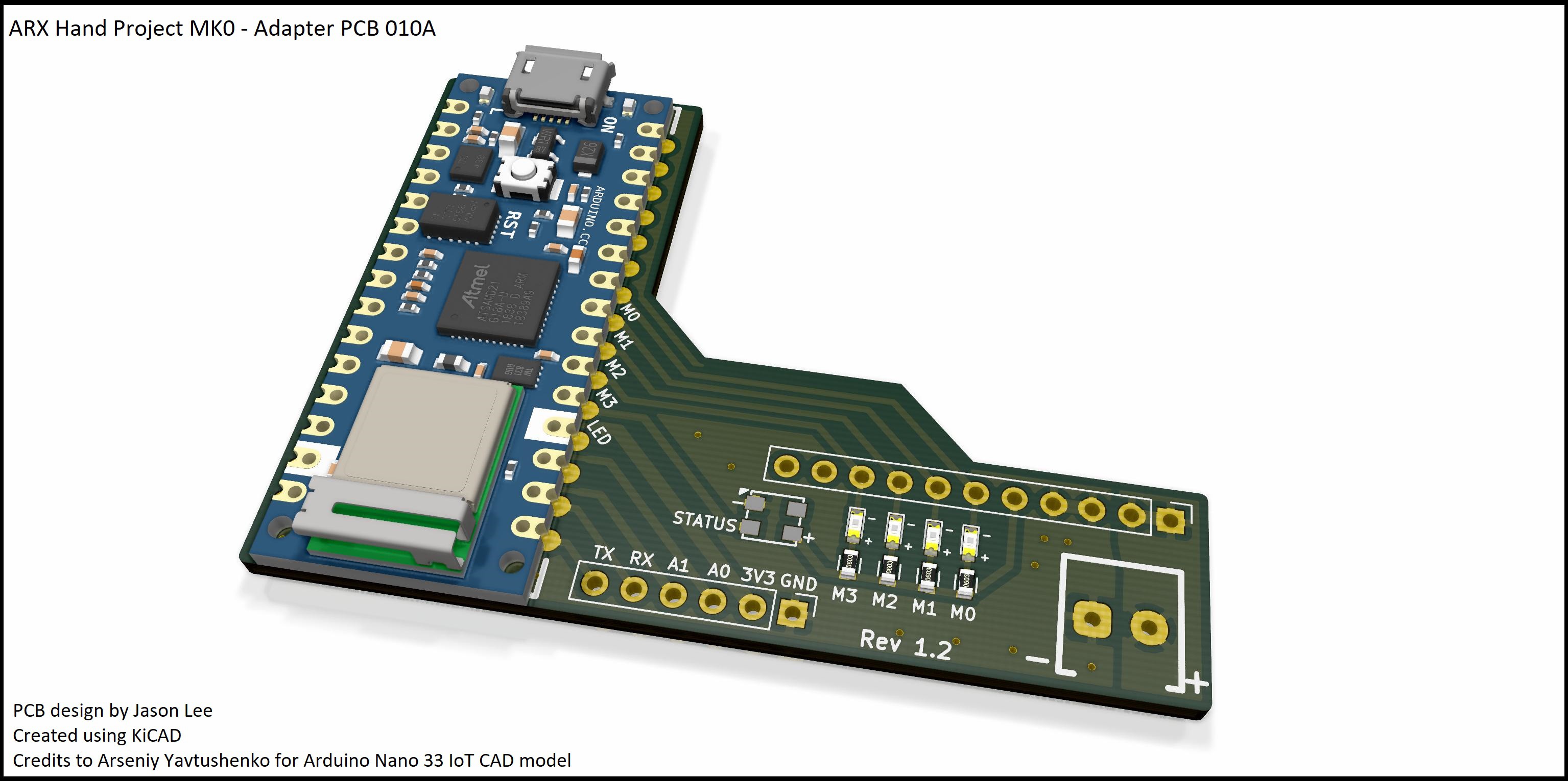
Adapter PCB made to accept an Arduino Nano or any similar board to interface with V1 I2C PCB. This reduces the requirements of having to manually wire the connections similar to the photos on V1 hand prototype. Adapter PCB also bring added debugging LEDs for quick diagnostics.
Features
- RGB Status LED
- Supporting LEDs for drivers that aren't on the V1 PCB
- Broken out pins for additional interfacing
- Screw terminal for power connections
Specs
- WS2812 LED on D2
- Mainly 5V based
- Breakout connections: GND, 3.3V, A0, A1, RX and TX
- Pull up LEDs added for RD0 to RD3

KiCAD: https://kicad-pcb.org/
Arduino 33 IoT CAD Model:
https://grabcad.com/library/arduino-nano-33-iot-1
 Supercell
Discussions
Become a Hackaday.io Member
Create an account to leave a comment. Already have an account? Log In.