 Jrsphoto
I picked up a VME backplane recently, not exactly necessary to power up the card but it will make things much easier. It will also allow me to add other cards, like a SCSI controller or VGA graphics controller. I'll likely make a cage around the backplane using 2020 extrusions and 3D print the card guides.
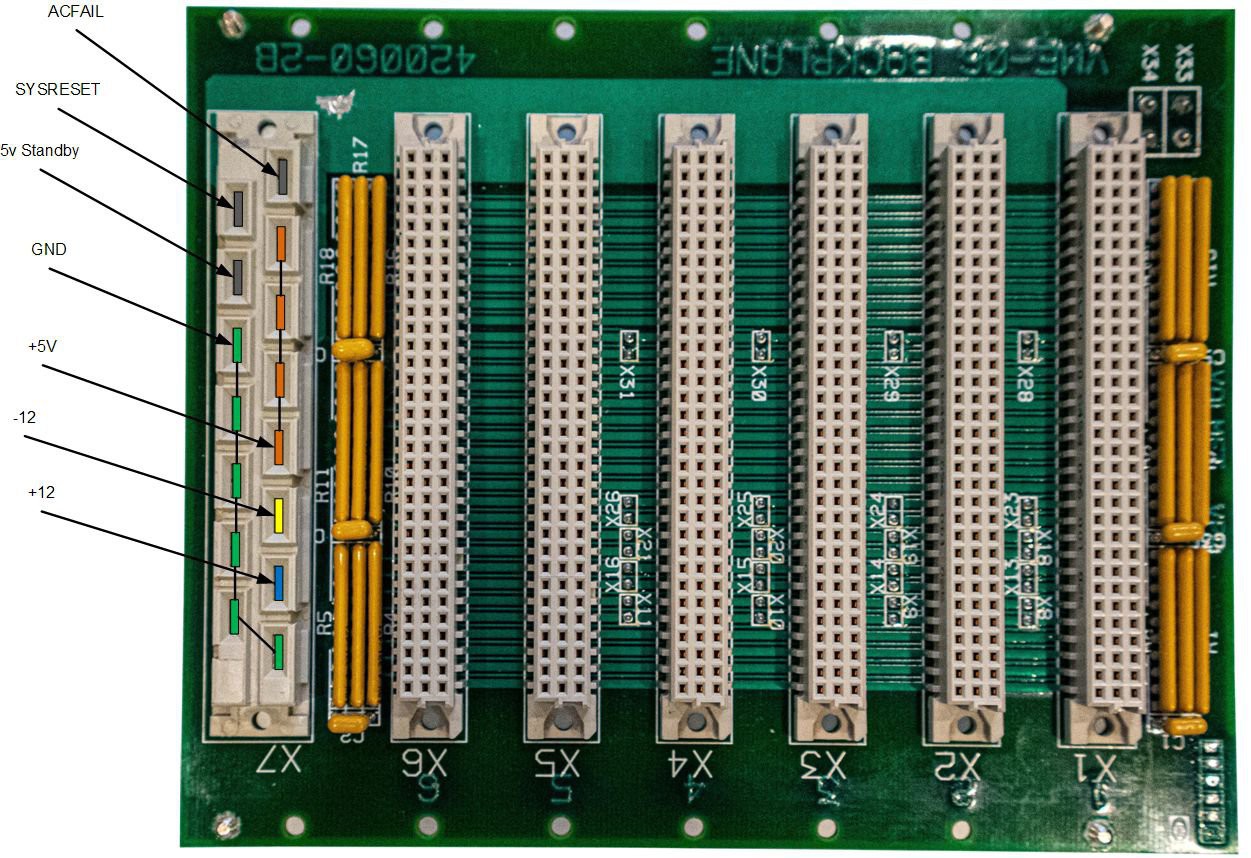
The one issue with this backplane is the rather non-standard power supply connection. This backplane was designed for use with a 3U Eurocard sized power supply, which would have had a mating connector and supplied power to the entire VME bus. I think I've got the pins mapped out to the proper voltages but I need to try find the pinouts of this connector before I actually power things up.
The power supply I will be using with this is a Power-One MAP80-4010. This switch mode psu outputs +5V @ 14A, -5V @ 1A, +12v @ 4A, and -12v @ 3A. Should be perfect for a small system with maybe 3 boards.
As always, if your reading this page and have information about the CPU board or this backplane, please let me know.
Discussions
Become a Hackaday.io Member
Create an account to leave a comment. Already have an account? Log In.