-
Built first card
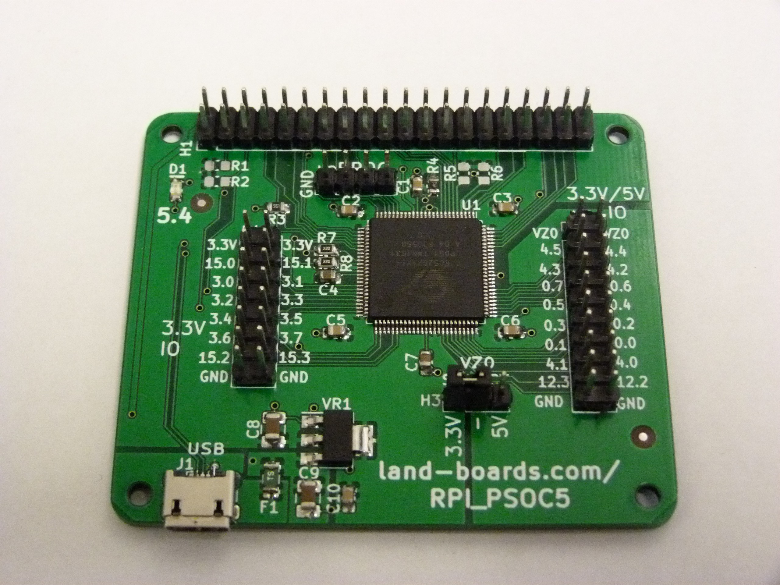
10/16/2019 at 11:10 • 0 commentsI built up the first card.
Downloaded a PSoC file which blinks the on-board LED. It worked.
Board is running a USBUART program which loops back USB data and I was able to type on the keyboard and get it to come back to the Host PC.
Testing Direct I/O
Normally I use Control Registers for LEDs but I'm messing around with direct access to the pins from the CPU. I tried direct access and it worked, too. I can now the Raspberry Pi GPIO pin high/low and it works. I had to set the drive mode for the pins to strong outputs and it worked. It might be better to have a separate function for ins/out rather than using the same function that sets the value to always set the drive mode but for blinking a bunch of LEDs it's no big deal.
-
Errata and notes
10/10/2019 at 00:59 • 0 commentsNote that that rev 1 PCBs I ordered are missing one trace from the PSoC to the Raspberry Pi I/O header. I've added the trace to the design files so it will be in Rev 2 of the board.
I ordered parts. The one part I was short on was the USB micro connector. I found one of the default parts in KiCad have four through hole mounting points and I think that could be a lot more durable than the ones which just surface mount and have a tendency to come off the card with frequent removal of the USB cable.
Other than the one trace everything else seems to be in order. We'll see when the boards get here how they operate. Given that JLCPCB delivered in less than a week with my 3-chip Z80 last week, I'm hopeful that the cards will be here quickly.
-
Raspberry Pi GPIO Emulation
10/10/2019 at 00:49 • 0 commentsLet's take a look at using the PSoC pins that connect to the Raspberry Pi connector (RPi connector pinout). In this case, we will attach one of our cards, the RPP-UIO-16 card. It provides header pins for each I/O pin on the Raspberry Pi 40 pin header. It also has an EEPROM for the ID of the card. There's also 16-bits of 3.3V to 5V bidirectional level shifters on the card to allow for 5V I/O.
Emulation of the Raspberry Pi GPIO is pretty easy in the PSoC.
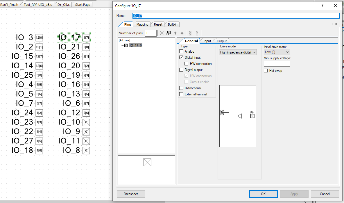
First, drop the Raspberry Pi pins onto a schematic sheet in PSoC Creator. They are software controlled pins so they don't need anything other than an input. I'm using the Broadcom BCM pin numbering order to make porting Raspberry Pi code simpler/compatible.
Here's the I/O pins on the schematic along with an example pin configuration.
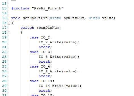
The pins are directly accessed with IO_XX_Read( ) and IO_XX_Write( ) functions which PSoC Creator makes based on the pin names IO_XX. They look like this (for write to IO17).
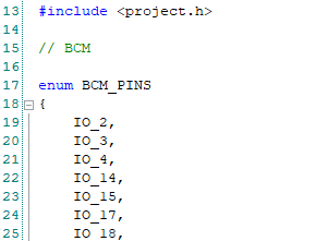
The pin list is an enumerated type in C. This sets a numerical index for the pins which the switch case (earlier) uses to decide which pin can be used. It's also passed to the routine as bcmPinNum. I don't know if the compiler will optimize the code (the correct case statement is a good thing for the compiler to optimize and using integers helps) but using an enum makes it possible to have a faster seek algorithm than a long series of if-then statement.
The calling routine from main( ) or whatever routine, calls them like this:
To access the ports, first set all of the Raspberry Pi pins as outputs and write out a zero.
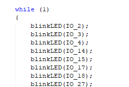
Then call the blink routine for each Raspberry Pi pin:
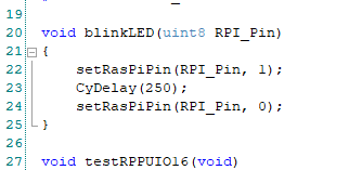
The blink routine looks like:
-
Clock Resources
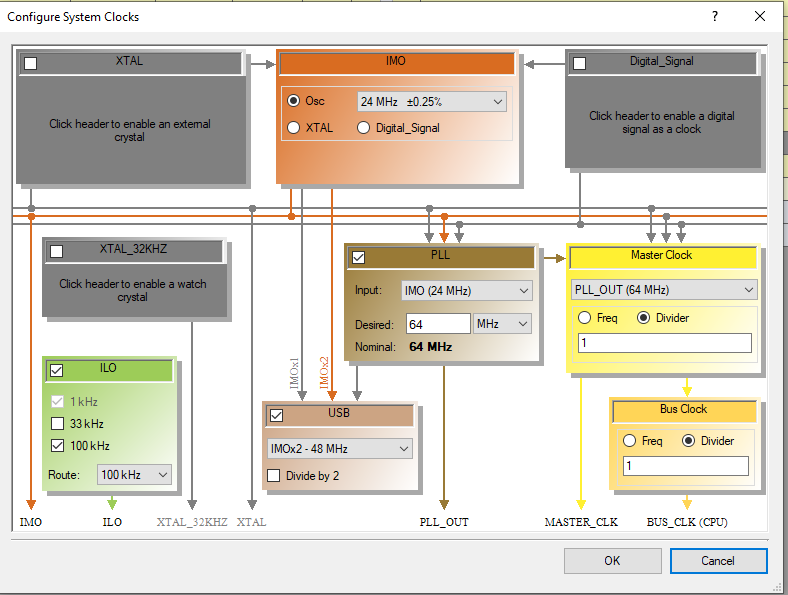
10/07/2019 at 22:28 • 0 commentsI only tweeked the clock resources a bit from the default values.
This sets the USB to the accurate 48 MHz. The PSoC CPU is running at 64 MHz. It all runs off the IMO which is accurate to 0.25%.
So, it looks like the FPGA as all GPIOs is an easy fit into the FPGA.
Time to order boards.
-
GPIO and the PSoC
10/07/2019 at 12:46 • 0 commentsThere's an interesting limit on the PSoC for output enables. Each 8-bit port can only have two output enables.
This makes creating a general purpose port difficult. Unless the pin is set to be open collector and driven low. With a pullup on the input. That could work. There would need to be a gate on the output which effectively disables driving the line low.
In order to check the pin assignments, I created a PSoC design file with all of the ports set up as GPIO lines. As noted above there are only 2 Output enables per block so this did limit the general case of I/O pin direction control on individual pins.
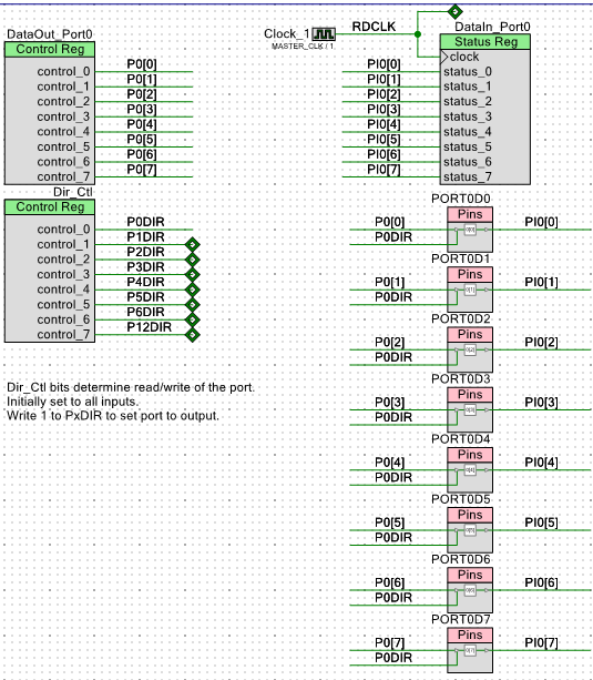
Here's what one 8-bit port looks like:
The Dir_Ctrl register sets the direction of the GPIO pins. The register powers up with all outputs at 0 so this means all of the I/O pins are input pins at power up.
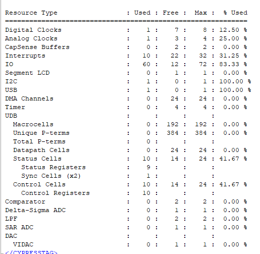
I made ports for all of the pins. This used the following resources:
This is less than half the Control and Status registers in the PSoC. Of course, some of these ports will be set up for specific functions (UARTs, etc).
-
Polishing the design
10/06/2019 at 17:04 • 0 comments- Added bypass caps near the I/O lines as recommended by the PSoC datasheet. We've had them on all our other cards.
- Beefed up paths to the power pins on the PSoC by moving around I/O traces.
- Resequenced ref des to make them in order l-, t-b.
- Checked 3D model. A great way to spot silkscreen inconsistencies.
Getting ready to order the PCB.
-
Pi Replacement Layout
10/04/2019 at 02:32 • 0 comments![]()
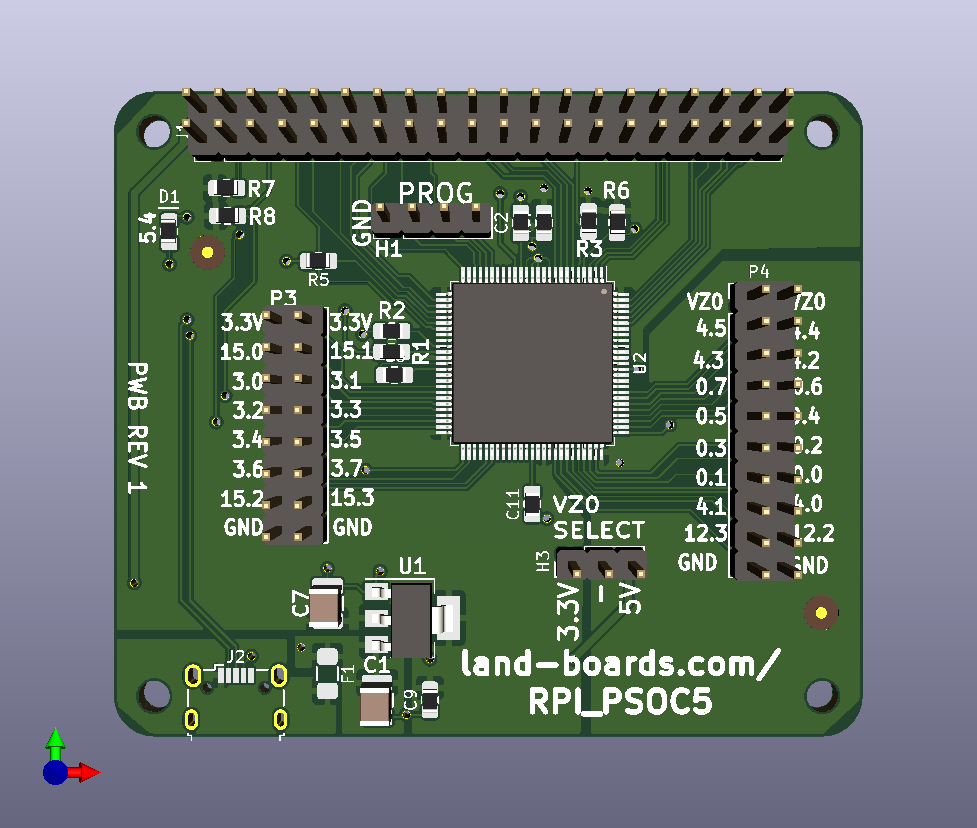
- The PROG (Programming header) could be right angle.
- Fuse on USB power protects the Host computer USB power and protects from rogue hats.
- 3.3V power regulator for PSoC and hat.
- 12 PSoC I/O pins @ 3.3V (P3).
- 16 PSoC I/O pins @ 3.3V or 5V (group selected by jumper H3)
- USB connector is relatively expensive ($2) but has mechanical mounting so it should be tolerant of a lot of connect/disconnects
Not Quite Useless Raspberry Pi Replacement
Make a Raspberry Pi replacement using a Cypress Semiconductor Programmable System on a Chip (PSOC 5)
 land-boards.com