 Stefano
The frame start to get populated:
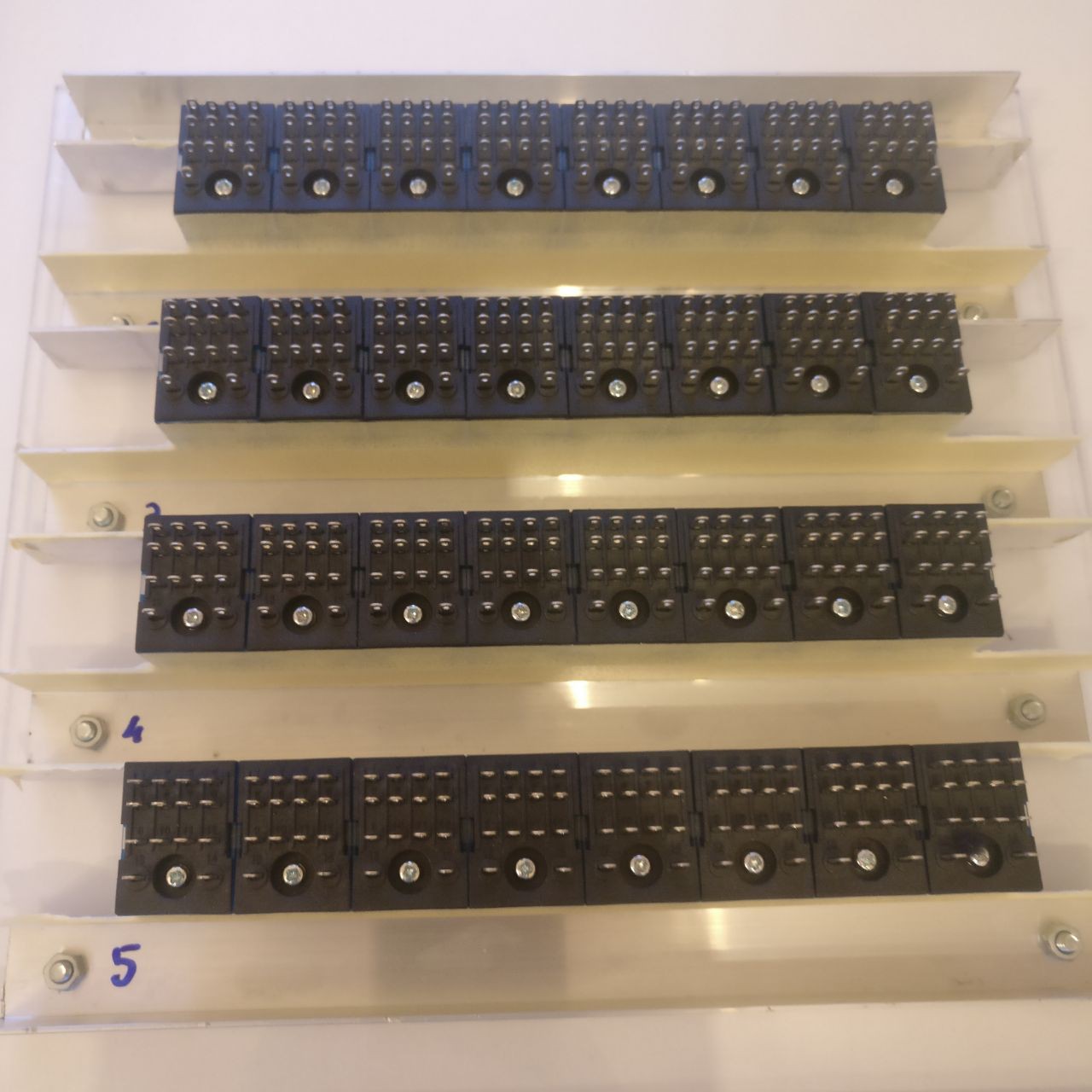
50 might be a little number of relays but surely is already providing quite an intricate mess of wires and a lot of headaches if not properly planned (and even if properly planned): at least let's try to manage at best!
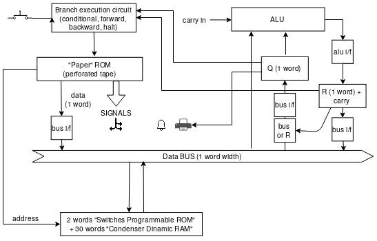
Following a bit more detailed overall schema of the PC (more details of the various circuits will come in later posts):
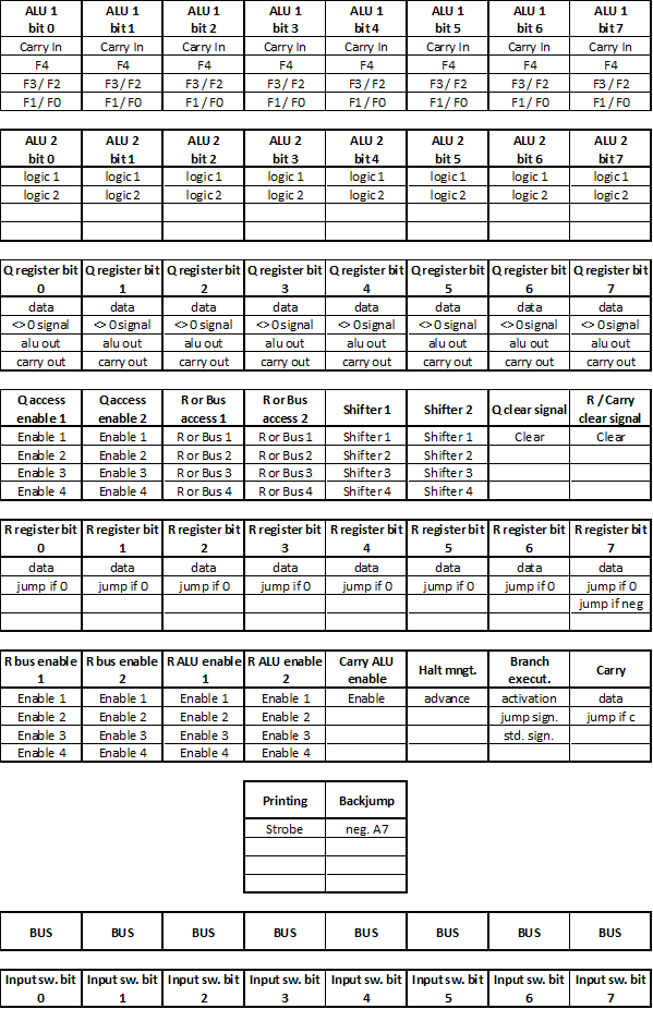
And below a tentative to put some order between units in the frame:
As of last image a drawing guide for the wiring of the first bit of the ALU (the famous "no dollars" one of @roelh):
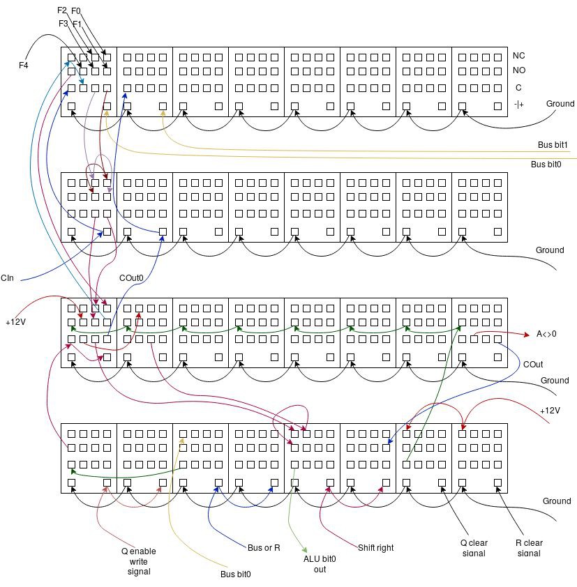
(the full layout of the MY4NJ can be found in first project log)
Discussions
Become a Hackaday.io Member
Create an account to leave a comment. Already have an account? Log In.