 Stefano
As mentioned the memory is one of the two remaining parts of the computer to be built (the other one being the mostly mechanical punched tape reader).
For this I've tried to see if a ready design was available, but until now I didn't find anything suitable. Many relays computer implementations I've seen are attached to modern static RAM with some adaptor. The others are using diodes, as the TIM8 one, but I'm trying to avoid them in the construction since they were not available in the middle of 1800.
The solution I'm thinking to implement is using just relays and capacitors. Not sure if it is the simplest as I'm always trying to push for, and I'm posting it here also to see if someone can improve it or suggest a new design.
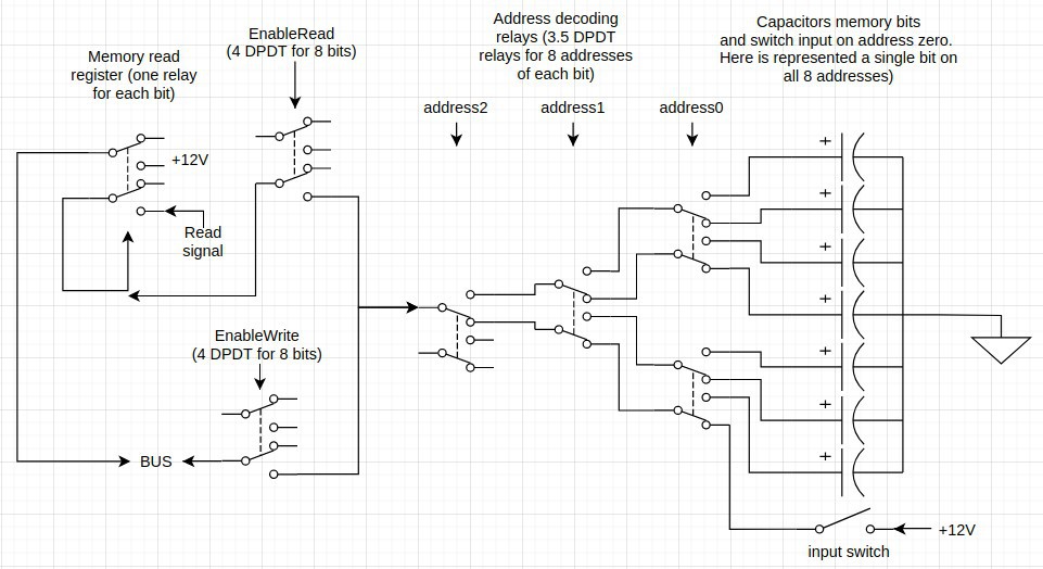
To write first erase content with EnableRead without Read signal, then switch off EnableRead and switch on EnableWrite and put on the bus what to write.
To read switch on the Read signal than EnableRead will load the Memory read register with the value that is being put on the bus. Release the Read signal when the value is not anymore needed on the bus.
Notes:
1. The data is stored on capacitors, the relays form just the "memory controller" part
2. Reading content "refresh" also the capacitors memory
3. One of the addresses (zero in the example picture) is filled with switches instead of capacitors in order to save one control line and two relays that else should be dedicated to input read
Relays count for 8 bytes (64 bits) memory:
+ 14 relays for address decoding (2+4+8)
+ 2 for EnableRead
+ 2 for EnableWrite
+ 8 for the Memory read register (can be dpdt)
= 18 4pdt + 8 dpdt relays (plus 56 capacitors and 8 switches to complete the circuit!)
Discussions
Become a Hackaday.io Member
Create an account to leave a comment. Already have an account? Log In.
another idea occured to me... why not have two muxes... you can support more memory that way. place the second mux on the ground side of the caps. Imagine if your current circuit were only the 0 plane of a 2d grid of caps... just a thought...
Are you sure? yes | no
Didn't get how the circuit should look like.
I did an intermediate design joining all bit at the same address on the negative side and all the bit of the same "2's power" on the positive side and putting relays on both sides (positive and negative), but this was creating loops and so I had to change it.
Are you sure? yes | no
maybe you've already tried this but instead of connecting all the caps in on big common connection to ground... multiplex their connections to ground that way you get 2x the address bits to the array of caps... just an idea...
Are you sure? yes | no
As reported I tried one design connecting separately all bits of each address to the ground (and selecting with relay the one that should connected each time), but this design do not work. The reason is because then you should connect more than one together on the positive side (the one that are disconnected on the negative side, and in my case was for example bit0 of all the addresses together, bit1 of all the addresses together, etc.), and this configuration is forming loops. As in a keyboard matrix you could avoid them with diodes, but I don't want to use them.
If you think you've some ideas try to write the schema or even prototype it, I'm more than happy to adopt each relay saver circuit if they would work!
Are you sure? yes | no
a buffer latch is a good idea! doesn't have to be the R register. hack on!
Are you sure? yes | no
It was to try to save relays! ... I'm an optimizer type! :)
Are you sure? yes | no
where is the refresh circuit? will the caps last long enough... prototype! id love for this to work, but i'd feel beter with a prototype or test version... good luck ! hack on!
Are you sure? yes | no
For how it's designed reading values immediately also refresh charge. So if needed each some time a memory read cycle can be done.
I prototyped an earlier version and worked. The capacitors were still able to be red after half hour without refresh.
Note: the capacitors I have (in abundance) are 100uF; they are enough for the DPDT small relays, but not for the 4PDT ones (1mF seems to be good for them); this anyway do not affect the relays counting since DPDT should be used just on buffer latch and for this just 2 contacts were used
Are you sure? yes | no
I don't see how a read refreshes the caps read... but 1/2 hour retention time wow! maybe it's better if you just build it, and i'll keep my ideas to myself
Are you sure? yes | no
If you look at the circuit, with EnableRead "on", the Read signal goes also to the positive side of the capacitor and charge it if the bit is 1 (or to discharge through the coil of the memory read register if the Read signal is disconnected, useful to clear memory).
Your doubts maybe doubts of others and your ideas might be good but will be surely unuseful anyway if not expressed! Not much discussions on this "niche" projects so please go on! ;)
Are you sure? yes | no
One idea I was pondering is reusing the R register also as the memory read register... This could be done, but then the memory could not be used in operations with Q since the result register is acting also as input! So no way unfortunately, since this is a must for proper programs.
Are you sure? yes | no