 Dave Pedu
I want to address a couple of specific problems of the old design:
- Power supply - my build of the old design uses a computer power supply (and later, a barrel-jack). A computer PSU is a bit unsightly. The design will be modular, but I'll use one of the popular pre-made power supply units, common in 3d printers.
- Hotswap connection - the old design cannibalized ethernet connectors for network and male/female dupont jumper connectors glued into the chassis. While this works, it's fragile and very easy to break. I don't think it would handle the 2.5A power requirement of the model 4 either. The new design will use a d-sub connector that both power and ethernet is routed through. This will add an inch or two of depth to case, but will make it possible to use other single-board computers later.
- Pi chassis - the old design depended on only the friction of the power and ethernet connectors to keep the pi in the chassis. The new design will use a 3d-printed locking mechanism to keep the Pi securely in place.
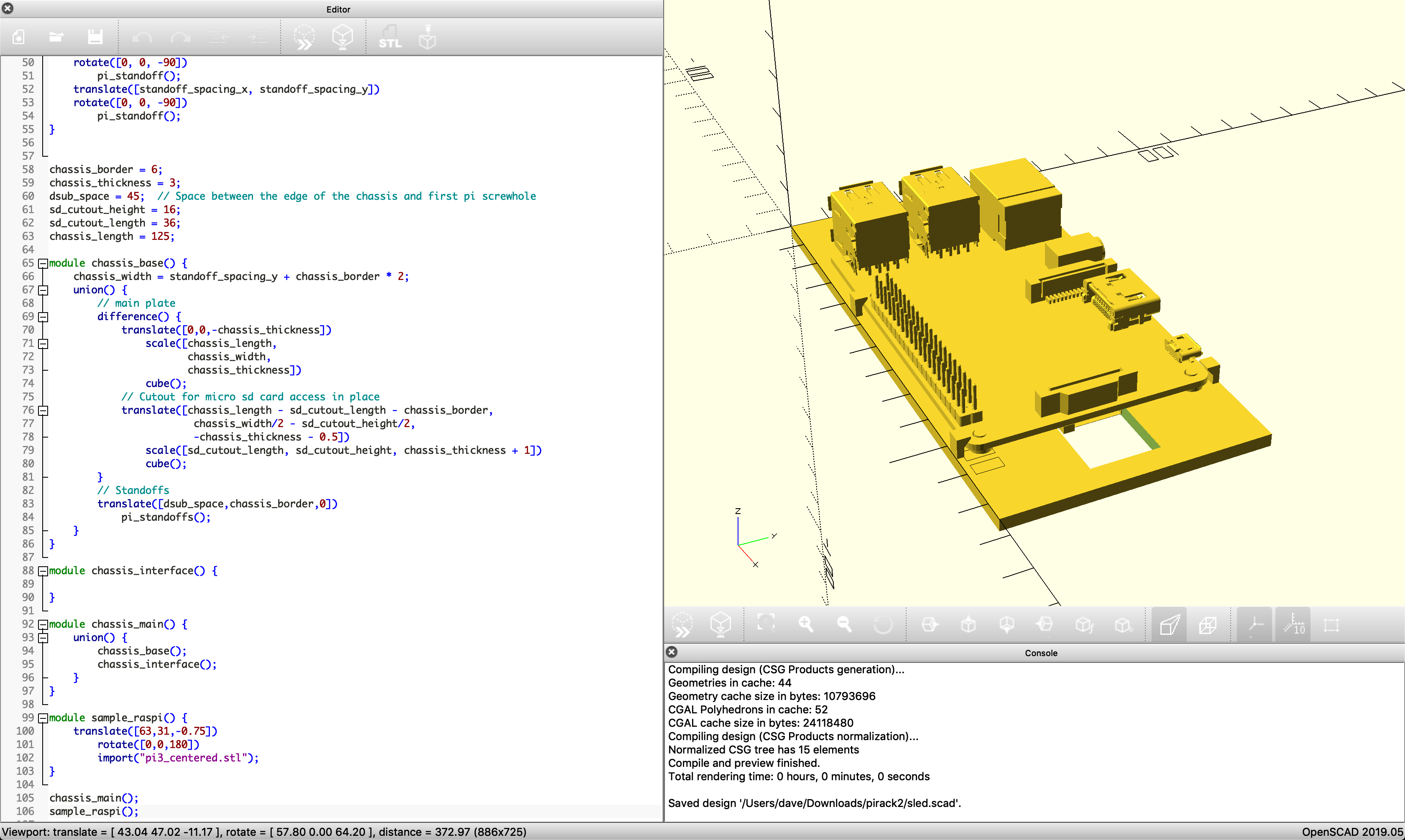
- Ease of editing the model - I was naive to 3d printing when making the old design, and manually drew it out in Sketchup. The new design will be done using parametric cad - OpenSCAD specifically. It was also drawn at a single configuration, holding exactly 6 of the Pi. Parametric cad being parametric cad, I want it to be very easy to make new configurations of the design.
I'm also only getting started! Here's a teaser for now:
Discussions
Become a Hackaday.io Member
Create an account to leave a comment. Already have an account? Log In.