Now that I can download code to the micro, it's time that I design and build the hardware.
As the MCU has only 8 pins, there is no much choice but multiplexing the LEDs and the buttons. The GPIOs of traditional 8051 are open drain with little to no internal pullup. Though newer derivatives including STC15 series have other options for the GPIO which include push-pull, it defaults to this weak pull-up configuration.
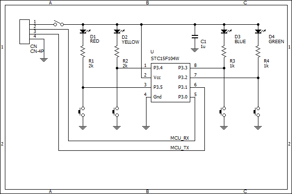
This is quite useful, as we can pull down the LEDs (with it's in series resistor) with both the GPIO and a tactile switch to ground, connected in parallel to it. Thus the following schematics:

The 4 pin header to the left is used to get both RX and TX (and GND) from the USB to serial adapted, but also to get 5V of Vcc from it. I used an 90 degrees angled header. The switch on the power rail is used to turn the device on and off, necessary also for programming.
The values of the resistors were chosen empirically to get good enough brightness, but not too much. The capacitor on the supply line is usually a good practice and the datasheet recommends using one, although you'll get with a smaller one than 1uF.
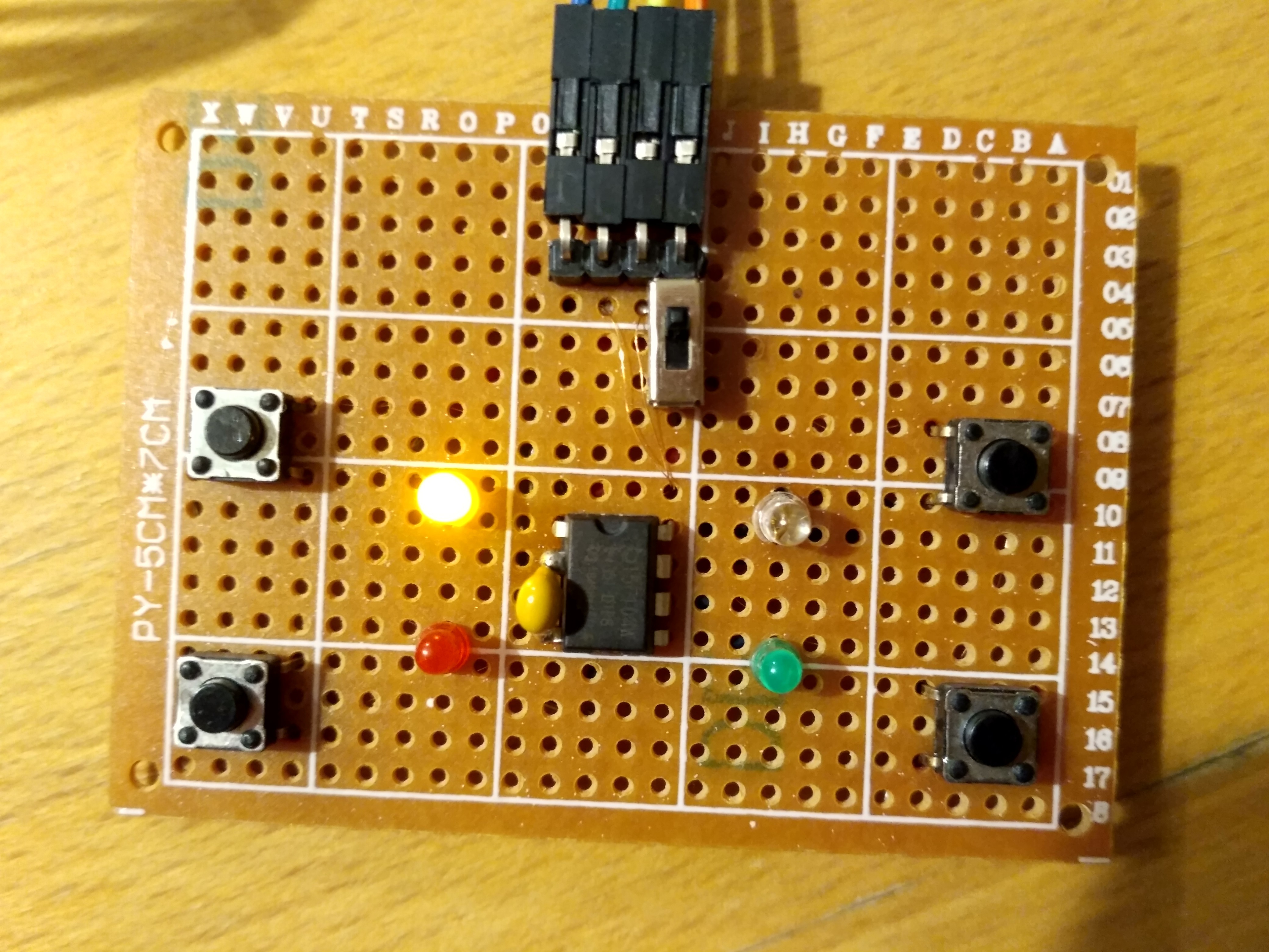
I have put it all on a protoboard. Here's the result:

I made sure that it works by pressing all the switches and see the LED lights up, and also by downloading a code that blinks them all. Good enough, the hardware is simple enough that I built it with no errors whatsoever.
 HummusPrince
Discussions
Become a Hackaday.io Member
Create an account to leave a comment. Already have an account? Log In.