Close
0%
0%

avrCIA / CANopen

CAN In Automation (CANOpen) - Stack for Atmel AVR's

Public Chat
Similar projects worth following
software-stack for AVR's providing CiA functionality

current state of implementation:

  • stack: CiA for ATcan* devices - 100% (done)
  • stack: extensions for MCP - 0% (not started)
  • user-software: monitor for CiA messages (done, python commandline tool)
  • firmware: bootloader - 100% (done)
  • user-software: bootloader - 100% (done, python commandline tool)
  • PDO-functions: 100% (done)
  • user-software: pdo tool - 100% (done, python commandline tool)
  • SDO-functions: 100% (done)
  • user-software: pdo tool - 100% (done, python commandline tool)
  • SDO- bindings: 100% (done)


So what's missing? I'm currently working on some hardware and firmware for CiA. On my list are typical components for home-automation:

  • relais-module with digital inputs and buttons (80% done, prototype exists)
  • shutter-module with display and manual override (5% done)
  • heating-actuator controler with manual override and LEDs (5% done)

20190613_112620.jpg

4 channel DIN-rail relais module PCB's

JPEG Image - 2.37 MB - 10/10/2019 at 11:26

Preview

IMG-20190613-WA0000.jpeg

4 channel DIN-rail relais module

JPEG Image - 851.94 kB - 10/10/2019 at 11:26

Preview

20190304_115626.jpg

6 channel push-button wall-mounted: PCB's

JPEG Image - 2.63 MB - 10/10/2019 at 11:24

Preview

20190304_115609.jpg

6 channel push-button wall-mounted: main-PCB

JPEG Image - 1.95 MB - 10/10/2019 at 11:24

Preview

  • hardware demo with working COBs

    Alexander Krause05/05/2020 at 09:38 0 comments

    I thought it might be a good time to publish some updates concerning this project ;-)

    demo setup

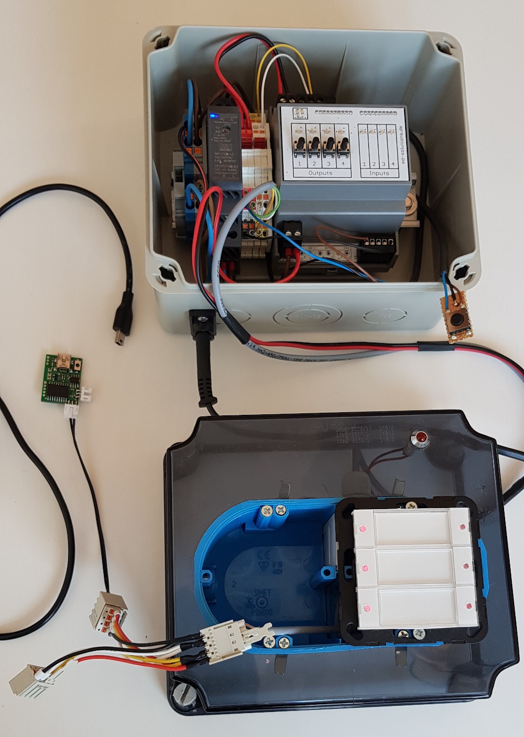
    Here you can see a litte demo setup, consisting of two CiA nodes: a 4 channel rail-relais-module and a button-module for wall installation.

    The setup is pretty easy function wise. Both nodes are on the same bus and are connected logically via COB-IDs (connection object, id's). The button-module sends some data to a COB-ID which is know for the relais-node and simply toggles its channels on or off. The relais-module also has some buttons for manual override and some digital inputs to toggle the corresponding relais channel.

    Here is a short movie: 

    I'm going a bit more into detail for those who are interested.

    Well, first of all, let's start with the COB-IDs. Concerning the toggling via bus we have to consider the button-node first. It has so called PDOs (Process Data Objects) or in other words a block of bytes which is send on process change. The button-node has internal objects for every channel which contain the button state and a timer.

    Each object is one byte long and looks like this:

     (counter++)&0xf)<<8) | (button_state&0xf)

     The counter is increased every 100ms as long as the button is pressed, so when we press the button the first byte will be 0x01, then 0x11, 0x21 and so on. Releasing the button creates 0x00. I'm creating objects like this to know whenever a button is pressed and for how long. If you only send the state itself, it's hard to measure the press-time for example if you'd like to implement a dimmer. Having this structure also has some other advantages. For example if you lose some frames (which in the world of CAN shouldn't happen). Losing the first press isn't bad cos you'll get another one 100ms later. Losing the release isn't as bad either cos you'll see a timeout and no other press frames will be send.

    CAN-wise you'll configure an TPDO (transmit PDO) which can contain multiple objects as long as the total length is equal or smaller 8 bytes. And each TPDO will get a COB-ID.

    So for the button-node the TPDO config of my firmware looks like this:

    TPDO:
      -
        conf:
          comm:
            cob_base: 0x180
            
        comm: [0x180,CO_TPDO_TT_MF,5,0,CANO_FLAG_ADD_ADDRESS]
        mapping:
          - [CANO_OA_RO,CANO_OD_FW_OFFSET+0x0011,1,8]
          - [CANO_OA_RO,CANO_OD_FW_OFFSET+0x0011,2,8]
          - [CANO_OA_RO,CANO_OD_FW_OFFSET+0x0011,3,8]
          - [CANO_OA_RO,0,0,24]
          - [CANO_OA_RO,CANO_OD_FW_OFFSET+0x0002,1,16]
    

     This describes one TPDO, with cob_base = 0x180. The resulting cob-id will be 0x180+node_address = 0x180+0x10 = 0x190 for the button-node.

    The mapping is static an can not be configured, consisting ob objects with index CANO_OD_FW_OFFSET+0x0011 = 0x6000+0x0011 = 0x6011 and 0x6002. The second number is a subindex (in fact the button-object is an array with 3 items) and the third number the bit count.

    So the first byte (len=8 bit) in the PDO are 8 bit of object 0x6011, subindex 1). The final byte btw. is a temperature sensor which is also send in this PDO (16 bits, final 2 bytes).

    Now all we need is a receiver, listening for cob 0x190 which is our relais module in this case. Equal to the TPDOs there are RPDOs which will map incoming PDOs into a devices objects. This for example looks like this:

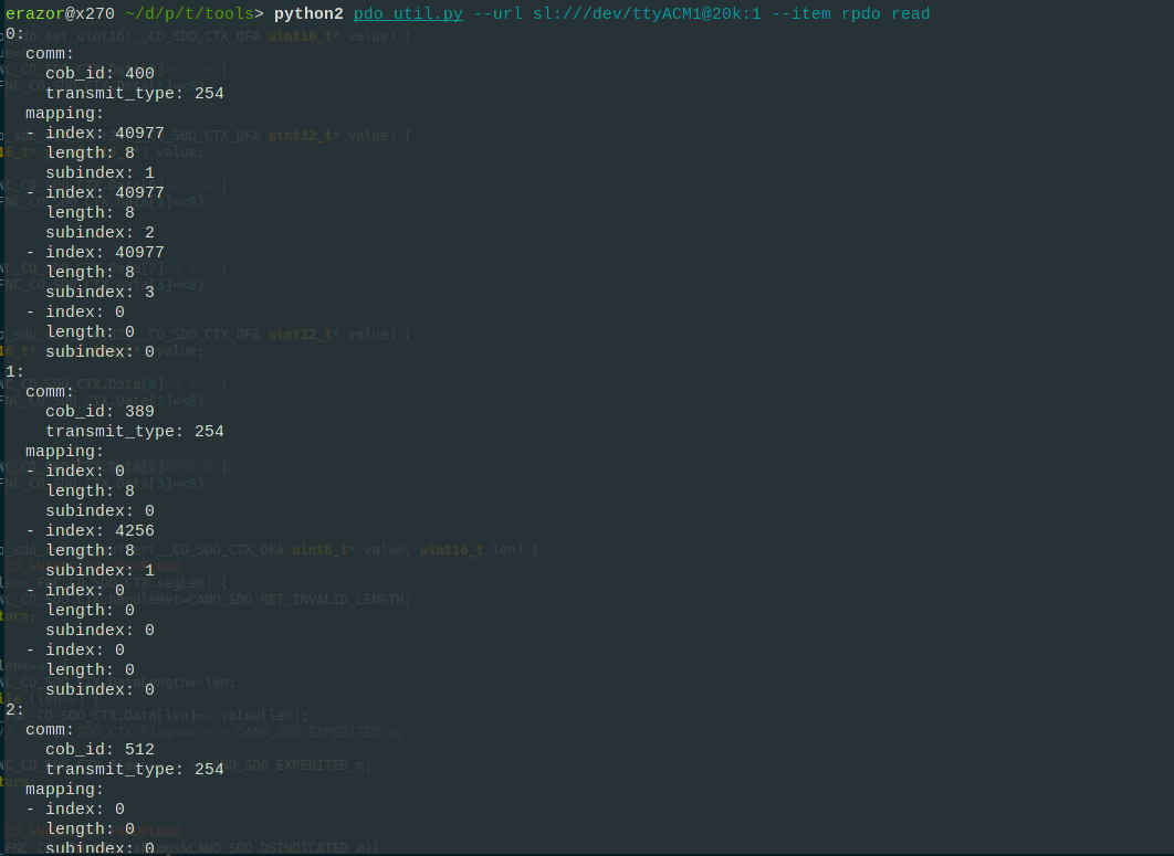
    The image shows the RPDOs of the relais-module. RPDO-0 has cob_id=400=0x190 -> TPDO from button-node.

    The mapping includes objects with index 40977=0xa011 . In the firmware of the relais-module are "incoming button channel objects" implemented. What they do is to evaluate the button state bytes of a button node which makes it possible to know if the button is pressed or not and for how long. For the relais-module this means, we have to toggle the corresponding output. Subindex 1 is the object for the first output channel, 2 for the second and so on. If you press multiple buttons on the button-node, it results only in one PDO being sent since the configured TPDO holds all 3 button-state objects.

    The second RPDO is for...

    Read more »

View project log

Enjoy this project?

Share

Discussions

Similar Projects

Does this project spark your interest?

Become a member to follow this project and never miss any updates