Construction:
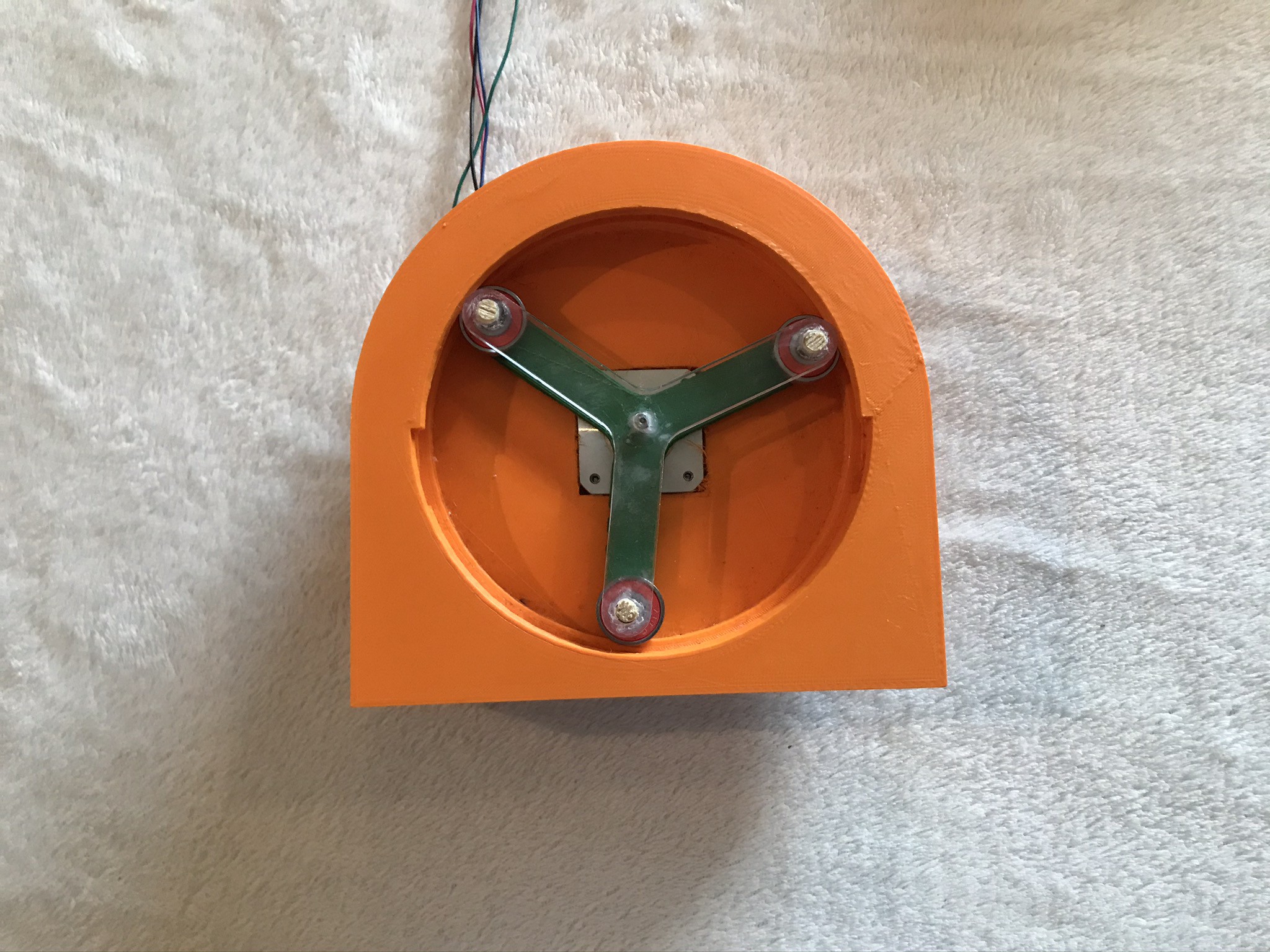
I completed the construction of my first prototype (CAD drawings in previous log).

Assembly Steps:
- 3D Print Casing and Rotors
- Fit bottom Rotor onto the motor's shaft
- Use Adhesive to attach Plywood rods onto the Rotor*
- Insert the Bearings onto the rods
- Use adhesive to attach the top rotor onto the plywood rods*
Issues and limitations:
- * These steps have been added as the bottom rotor when attached was too weak to withstand the forces and as such an alternative rotor was used which is similar to the top rotor. This meant that instead of the bearings being held in place with the rotor's extrusions, a plywood rod had to be used to hold the rotors and the bearings together and as such an adhesive was used.
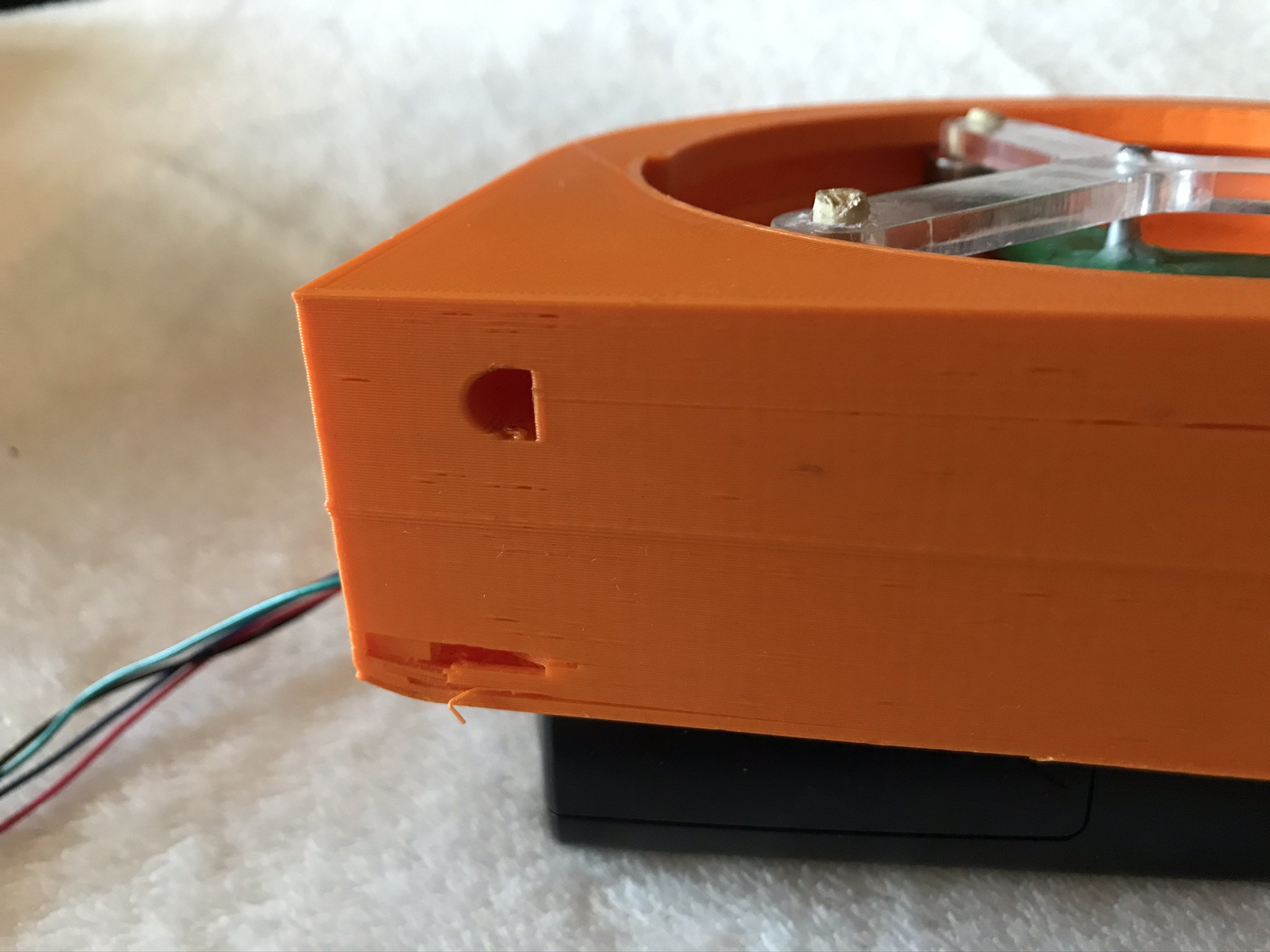
- Inserting the tube into the designated hole ( Shown below) in the casing was quite challenging as the design did not take into account the tolerance and manufacturing error when using 3D prinitng. This was also the case when fitting the motor into the casing.

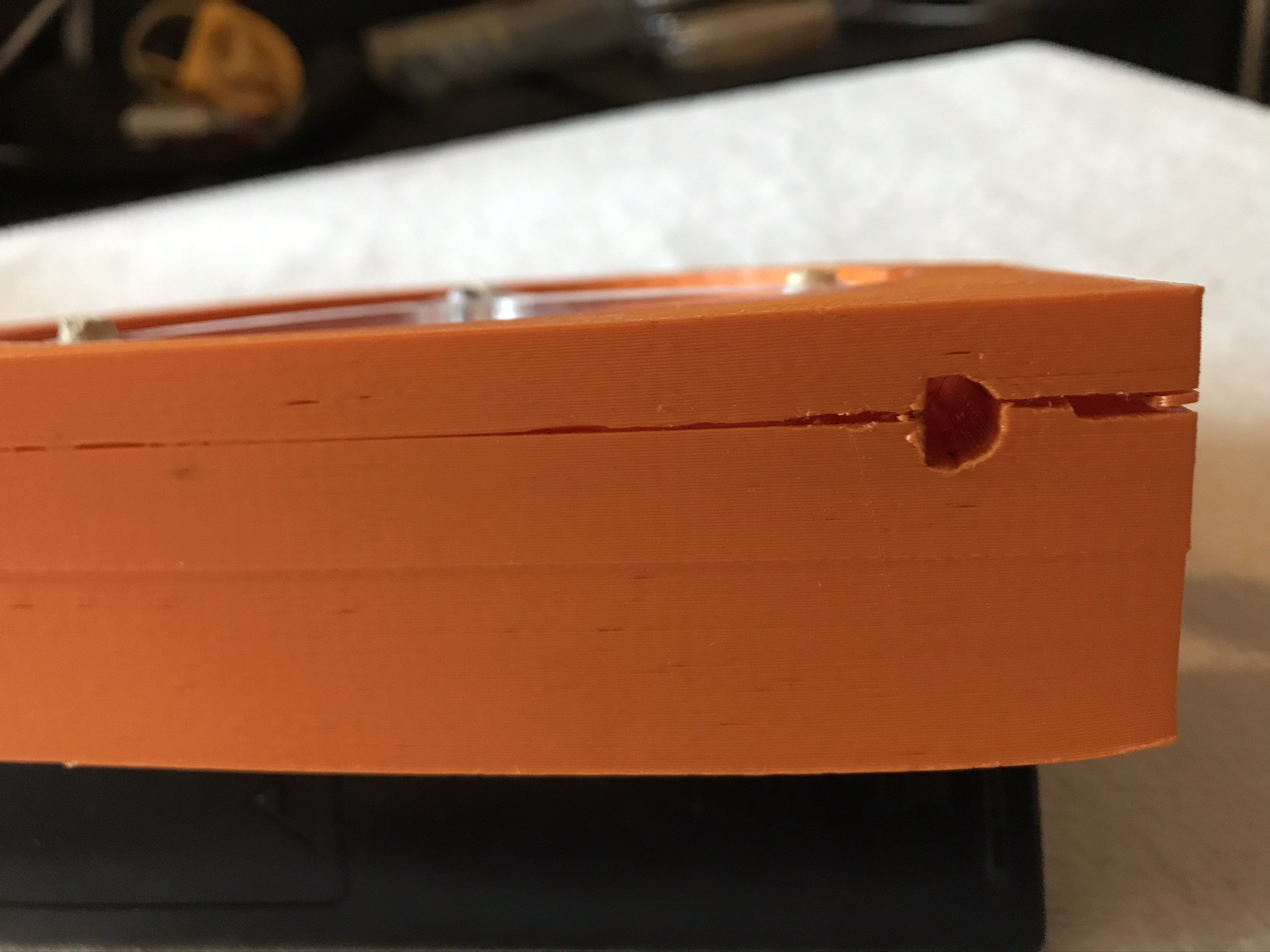
- Additionally, when the pump was operational, parts of the casing structure initiated cracked that later propagated as shown below. While these cracks did not affect the pump's operation they most definitely will affect the overall structure integrity.

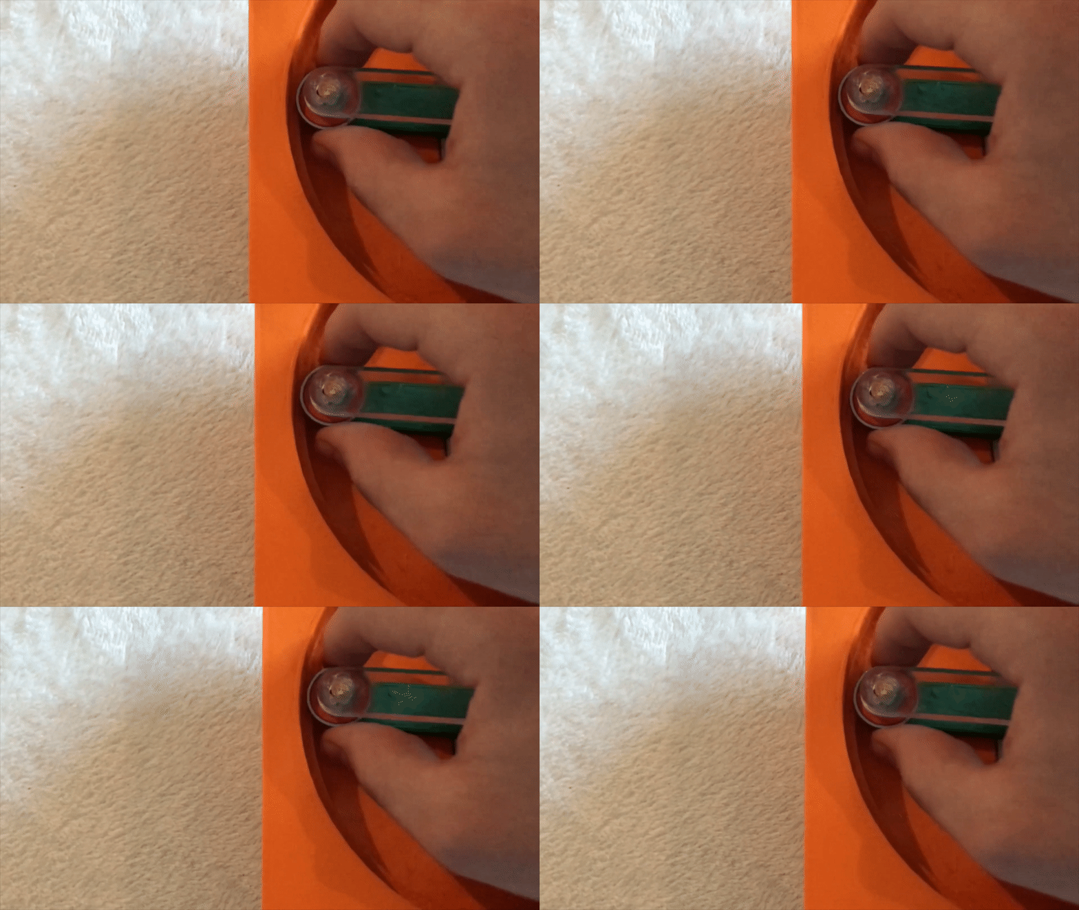
- Finally, the plywood rods' diameter used was not large enough to ensure the bearings are in pure rolling. As shown below one of the bearings wiggles easily in place and this will significantly affect the performance of the pump.

 Ali
Ali
Discussions
Become a Hackaday.io Member
Create an account to leave a comment. Already have an account? Log In.