 Redgeneral
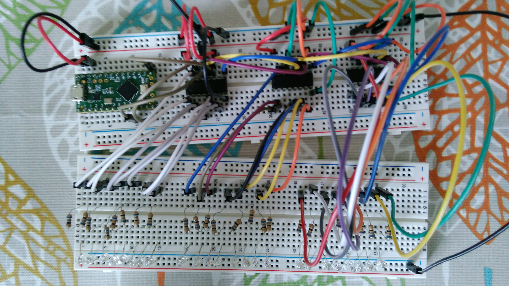
Three 74HC595 chips will be used to drive the 24 columns of the keyboard's button matrix. I built a prototype on breadboard to ensure the circuit design and code were correct, As this was just a test of the columns, LEDs are used instead of buttons.
Code:
// -----------------------------
// teensy 24 led columns -
// cycles through to light up
// one LED at time
// -----------------------------

// connections to 74hc595
  int latchPin = 8;
  int clockPin = 13;
  int dataPin = 11;

// count
  int count = 1;
  int countTotal = 24;

// shifting values
  byte patterns[8]={
    B00000001,
    B00000010,
    B00000100,
    B00001000,
    B00010000,
    B00100000,
    B01000000,
    B10000000
  };

// temp values
  byte tempA = B00000000;
  byte tempB = B00000000;
  byte tempC = B00000000;

void setup() {
  // put your setup code here, to run once:

  // set serial pins to output
    pinMode(latchPin, OUTPUT);
    pinMode(dataPin, OUTPUT);
    pinMode(clockPin, OUTPUT);

}

void loop() {
  // put your main code here, to run repeatedly:

  //update and reset
    if (count<9){
      tempA = patterns[count-1];
    }else{
      tempA= B00000000;
    }

    if (count<17 && count>8){
      tempB = patterns[count-8-1];
    }else{
      tempB= B00000000;
    }

    if (count>16){
      tempC = patterns[count-16-1];
    }else{
      tempC= B00000000;
    }


  //write to shift registor
    digitalWrite(latchPin,LOW);
    shiftOut(dataPin, clockPin, MSBFIRST, tempC); //3of3
    shiftOut(dataPin, clockPin, MSBFIRST, tempB); //2of3
    shiftOut(dataPin, clockPin, MSBFIRST, tempA); //1of3
    digitalWrite(latchPin, HIGH);

  //wait
    delay(500);

  //loop variable
    count++;
    if (count>24){
        count=1;
    }
}
Discussions
Become a Hackaday.io Member
Create an account to leave a comment. Already have an account? Log In.