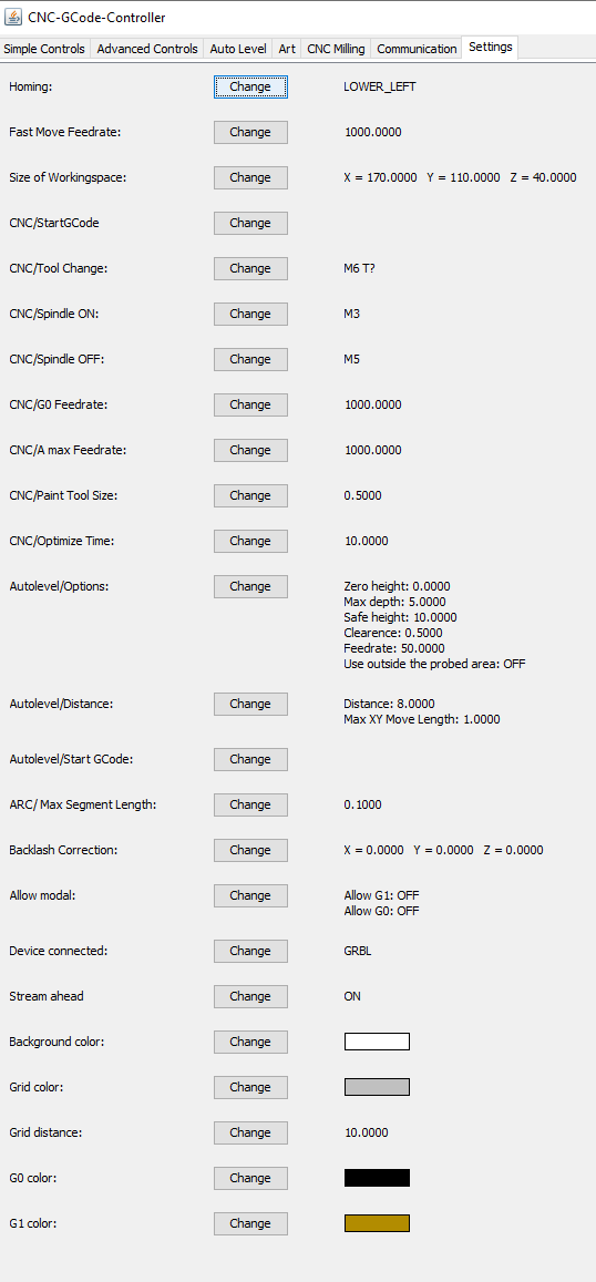
Okey, here is where the fun gets a but more interesting. I usually use my own software but cnc-gcode--controller has the amazing advantage that it can do proper bed leveling. However, the software was written in Java and oh my god I am not a friend of Java.
Since I use my own PCB milling machine, we need to send some amount of gcode commands to make this all work properly:
First, we need to home the machine with
$H
After this, my machine is ready to mill the top layer with the 0,0 point at the bottom left corner.
Now, we need to z-probe the actual z-height of the board and then reset the coordinate system for Z. We will probe at -35mm and a very slow feedrate of 20mm per minute. After successful pprobing, we reset Z to 0.
G38.2 Z-35 F20
G92 Z0
Now, we can actually do the autoleveling using cnc-gcode-controller:
It is important to understand that cnc-gcode-controller needs a positive number in the Max depth configuration. Otherwise it will just stop above the surface reporting an Alarm.

I also deleted the Autolevel/Start GCode as it always runs back to the bottom right of my bed for no reason.
The bed is now level for top side milling. Nothing should be changed anywhere at this point. Load the nc file and start the milling process.
Under CNC Milling, Load the file for top side, select the checkbox for AutoLeveling and hit Milling.
After the top side is done, I am discussing if drilling now or later is preferred. There is a good argument against it: AutoLeveling the bottom side with holes in the board already is literally Russian Roulette.
However, the AutoLeveler in CNC-GCode-Controller only works with positive coordinate systems, which is really really silly. Most PCB generators use a negative coordinate space for either side of the PCB to simplify the alignment of top and bottom side. This should be improved and I think about working on this myself. But I currently don't have time to do that.
To mill the bottom side, the coordinate system needs to be changed. On my machine, I use a negative x-axis:
G92 X-160.3
G0X0Y0
This will reset the coordinate system and bringing the machine to 0,0 will move the tool head over to the bottom right of the table.
Now, the z-height must be recalibrated using the same command as above.
I strongly suggest moving a bit away from the X0, Y0 coordinate first to get a more reliable Z=0 reading.
G0 X5 Y5
G38.2 Z-35 F20
G92 Z0
UNFORTUNATELY, the autoleveler does not work for negative coordinate spaces so the bottom side must be milled blind! I haven't found a workaround for this, yet.
For the outline milling, we change the tool head over to the 1mm endmill, calibrate the Z-height as above and hit mill. This should finalize the CNC process.
All that's left to do is to clean up the board and solder it up.
During the writing of these notes, I realized, I have my X-offset set up 0.5mm too far. This results in a mediocre board that I can make work but it's not as pretty as it should have been. Anyways. I'm writing this, so that I don't forget everything next time I'm making a single board.
UPDATE:
I figured out a workaround for this issue:
Configuring GRBL to invert the X-axis after moving to the bottom side coordinate system removes the requirement to work in negative space. ($3 = 1 // or other settings: in my case XYZ all need to be inverted: $3 = 7). In this case, the entire mirroring of the bottom side PCB can be ignored.
 Timo Birnschein
Discussions
Become a Hackaday.io Member
Create an account to leave a comment. Already have an account? Log In.