 Timo Birnschein
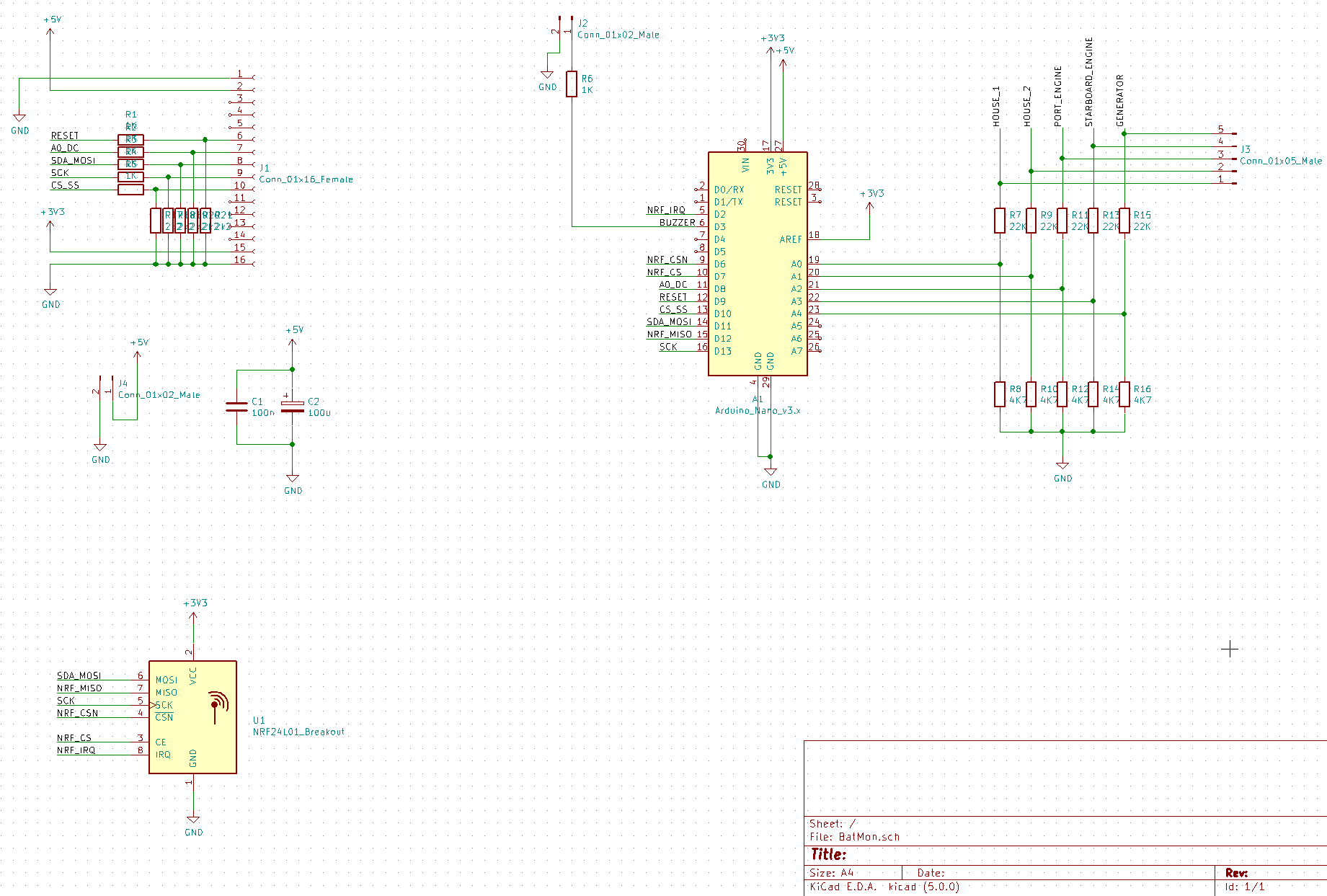
Since I cannot possibly put a bread board to permanent use in a marine environment, I created the schematics of the breadboard in KiCAD. The whole thing is rather simple.
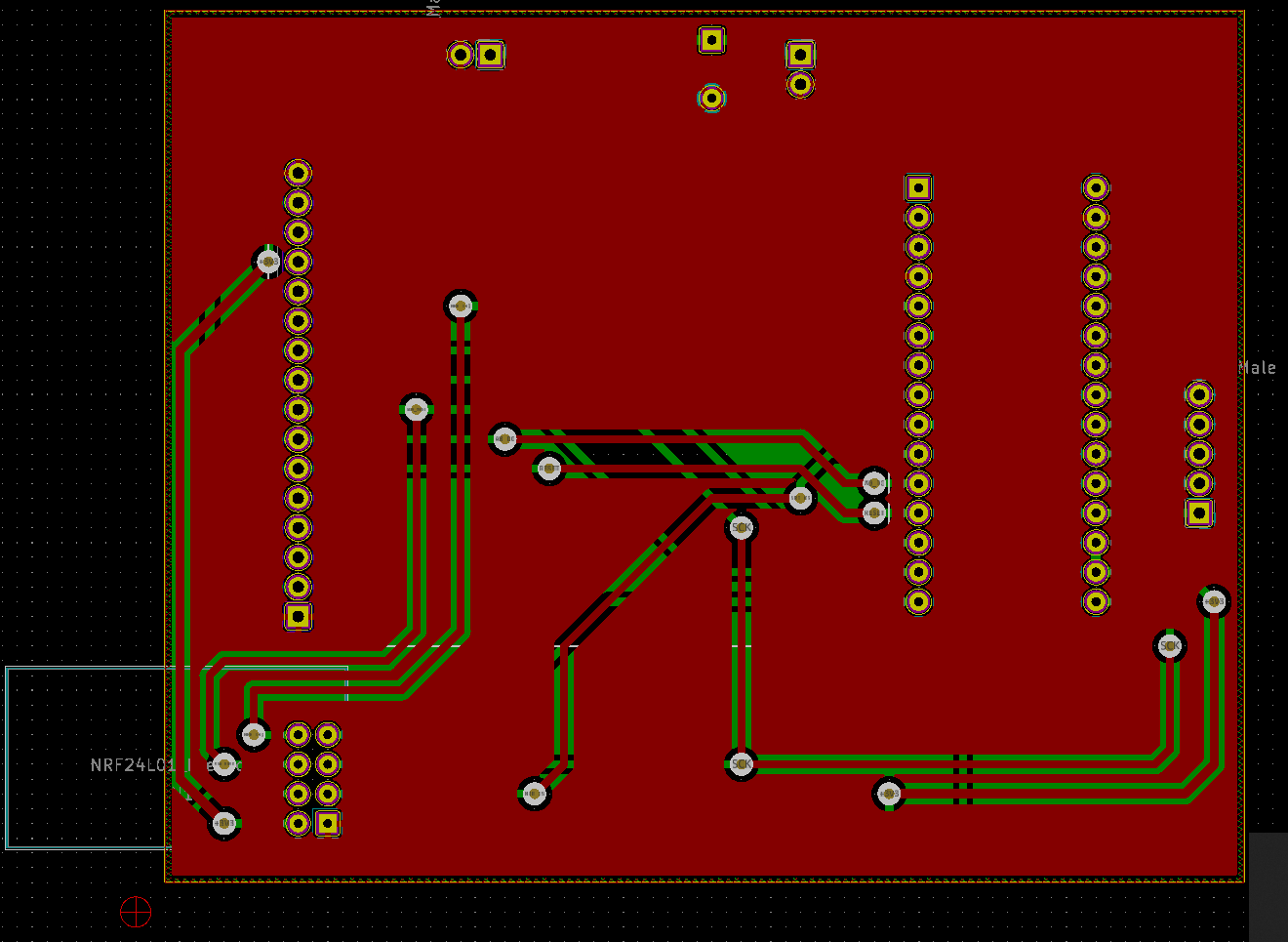
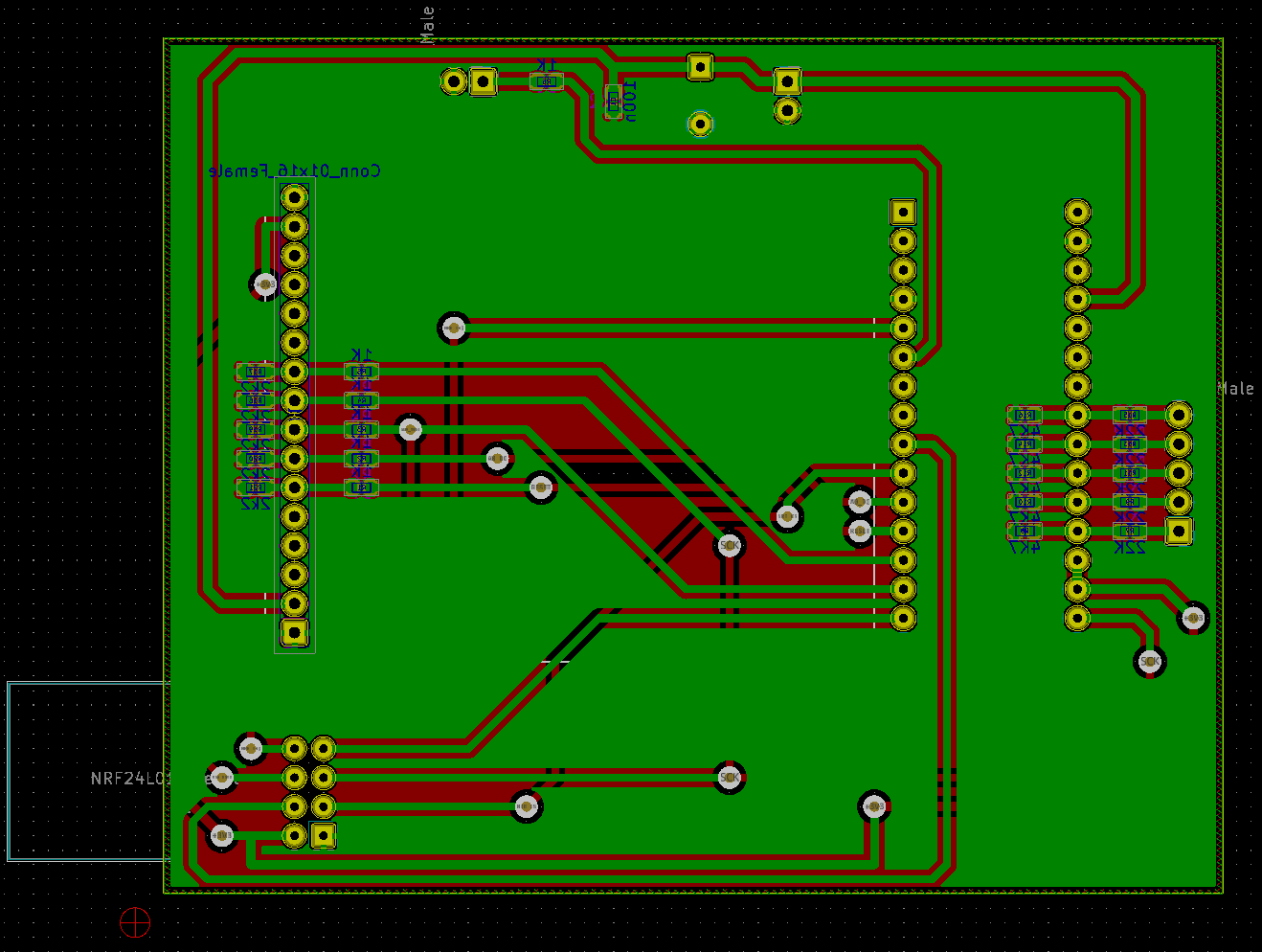
And here the board:
For the display I am using, it is necessary to divide the voltage of the IO lines down to roughly 3.3V. I use 1K and 2.2k resistors for this.
For measuring a total of 0V - 18V, I use 4.7k and 22k resistors as voltage dividers.
Discussions
Become a Hackaday.io Member
Create an account to leave a comment. Already have an account? Log In.