So we've been talking about the bus for some time. But when building a CPU we need two things from the bus:
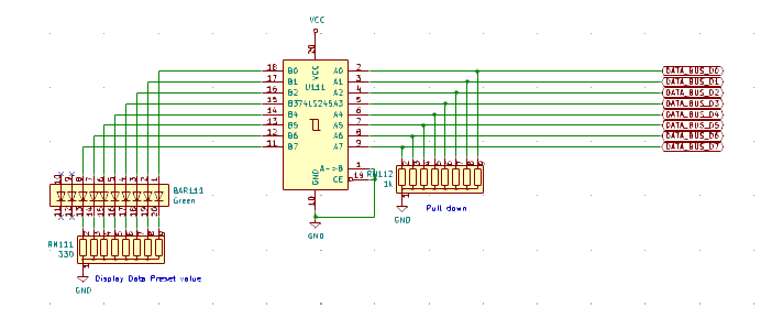
- see what is going on (visualize the value currently set on the bus)
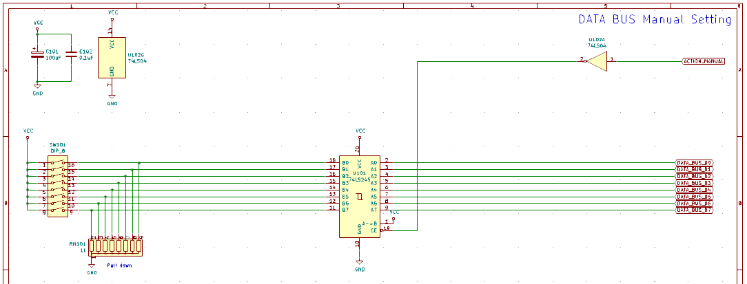
- manualy input a value if needed (for instance when trying to test a register, we need to set a known value on the bus to make sure the register can store it register_in and send it back register_out)
For this I have built a simple module that manually sets the value of the bus and displays the value of the bus.
However, there are a few contraints to take into account when building such a module:
- You need to set a default value for the bus. if a line of the bus is kept hanging (not connected to anything), there are chances that you will get either random values or unexpected behavior. This is called terminating a bus. It is usually done by connecting each line of the bus to a known value (Ground or VCC - 0V or 5V) through a resistor (called pull down or pull up).
- It is not a good idea to plug LEDs directlly to the bus as they can draw many milliamps from the bus and eventually overload the IC that is active on the bus. To prevent that, a buffer was added (as usual a 74HCT245).
- We are using standard DIP switches to set a value, but as explained above, the value is actually not directly connected to the bus but with a 3-state buffer and an action signal
In the end this module is quite simple with only 2 74HCT245, a bunch of LEDs and resistor networks (it is easyer to use a resistor network than to manually plug 8 resistors).
[Note: do not forget the pull down resistors on the DIP switches otherwise the line would be seen as hanging when the switch is opened]
[note : the NAND gate is used as an inverter, juste because there was one available near the module]
Manual setting of the bus balue:

Displaying the Bus value and bus termination:

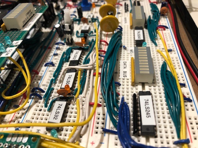
Preview of the Breadboard prototype (right of the photo):

 Ced
Ced
Discussions
Become a Hackaday.io Member
Create an account to leave a comment. Already have an account? Log In.