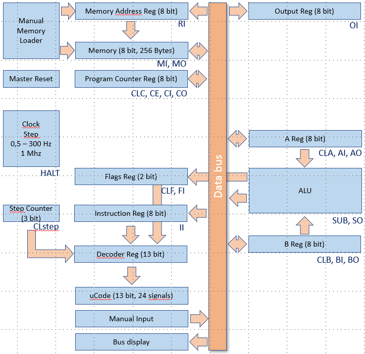
All the initial modules are now built, it is time to document the list of Micro Instructions.
Here is a map of all the available Micro Instructions assigned to each modules:

[unless specified, all actions are synchronous on the CLOCK_MAIN clock signal]
A register
- CLA : Clear A : reset value to 0 - Asynchronous
- AI : A register In : Load A register value from bus
- AO : A register Out : publish A register value to bus
B register
- CLB : Clear B : reset value to 0 - Asynchronous
- BI : B register In : Load B regisister ter value from bus
- BO : B register Out : publish B register value to bus
ALU & Flags
- CLF : Clear Flags : reset flags value to 0 - Asynchronous
- SUB : Substract function : apply substract function (default is Add)
- SO : ALU Out : pubish ALU result value to bus
- FI : Flags In : set flags based on current value of ALU output
Instruction register
- II : Instruction In : Load instruction register value from bus
Step counter
- CLstep : Clear Steap : reset counter to 0 - synchronous on CLOCK_STEP clock signal
Clock
- HALT : stops the clock
Program counter
- CLC : Clear Program Counter : reset Program Counter value to 0 - Asynchronous
- CE : Program Counter enable : increment Program Counter value by 1
- CI : Program Counter In : load Programl Counter value from bus
- CO : Program Counter Out : publish Program Counter value to bus
Memory Address Register
- RI : Memory Address Register In : load Memory Address Register value from bus
Memory
- MI : Memory In : Load value from bus and store it in memory at the address specified by the Memory Address Register
- MO : Memory Out : publish value of memory at address defined by the Memory Address Register to the bus
Output Register
- OI : Output In : load Output register value from bus
Some of these signals will be connected to the Instruction Decoder, some are connected to the reset switch only.
 Ced
Ced
Discussions
Become a Hackaday.io Member
Create an account to leave a comment. Already have an account? Log In.