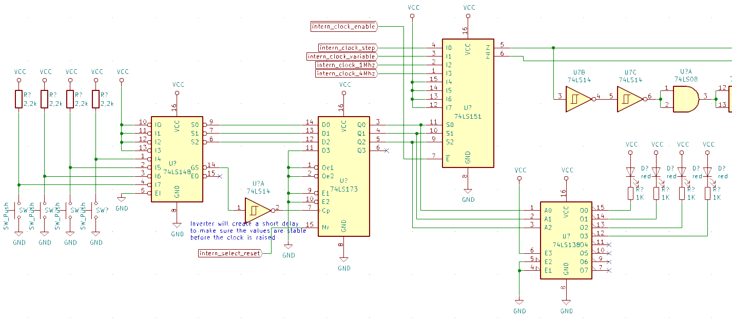
This new version of the CPU required a new approach for the clock. This is why I thought it would be much easier to use pushbuttons instead of slide switches. That is where the idea of a 4 radio-button style clock selector came from.
There are 4 clock signals to select from:
- Manual
- Variable
- 1Mhz
- 4Mhz
We needed the following features:
- 4 inputs (pushbutton) to select the clock
- 1 reset signal to reset to manual (at startup but also on HALT and BREAK signals)
- 4 LEDS to display the selected clock
- A signal selector to select and output the proper clock signal
We have selected a combination of 4 elements to perform this task:
- A 74LS148 (8 way priority encoder) that will output 3 bits depending on which pushbutton is pushed and a active-low signal when a pushbutton is pressed. Only the first 4 inputs are used, therefore only 2 bits are required but we still keep 3.
- A 74LS173 (4 bit register) to store which button was selected (3 bits are enough, the 4th one is kept high).
- A 74LS138 (8 bit decoder) used to activate a LED corresponding to the stored entry, again, only 4 outputs are used
- A 74LS151 (8 way multiplexer) to output the selected clock

So how does it work?
- When pressing a select button on the left, the 3-bit output of the 74LS148 is set to the binary value corresponding the pressed button (0b000 for input 7 to 0b011 for input 4, inputs 3 to 0 are not used). At the same time, the GS signal (active low) is set indicating that a button is being pressed. This signal will be used as a clock for the next step to indicate to store the value of the 3 bits
- The 74LS73 is a 4 bit register, it will store the binary value coming from the 74LS148 presented on its inputs when the clock pulse input is rising (3 bits + 1 value kept low). As the GS signal is active low, we first need to inverse it to get a rising edge instead of a falling edge. This will also create a small delay making sure that the levels of the 3 bits are set before triggering the register. Finally, the master reset input will be used to reset the value to 0b0000 corresponding to the pushbutton 7.
At this step we have a valid binary value stored in the register to represents the current selected channel. We then need to perform 2 tasks:
- Display in a human readable manner the selected channel instead of binary, basically either a Hex display or simply 4 leds, on per input
- Select the clock signal to output
To display the selected channel, we will simply use a 74LS138 (8 output decoder). It will light the proper LED according to the stored value in the register. Note that the outputs of the 74LS138 are active low.
To select the clock, we will use an 8-channel multiplexer (74LS151): based on the binary value inputted on its 3-bit input, it will select and output the right clock channel. Note that there is a side benefit as this chip also provides the inverted signal.
 Ced
Ced
Discussions
Become a Hackaday.io Member
Create an account to leave a comment. Already have an account? Log In.
Hi Michael, good question, but you acutally do not need debounce as the combination of the 148 and the 173 act as latch. The first time a contact is made on one pushbutton, the GS pin of the 148 acts as the clock for the 173 and latches the value. This clock signal is not linked in any way with the CPU clock. Even if multiple bounce arise, the value is latched and therefore will not change on the bounces. Now if multiple pushbuttons are pressed at the same time, the 148 acts as a priority encoder, therefore only the most significant button pressed will trigger the output.
Hope I make sense.
Are you sure? yes | no
So where is the button debounce? But I suppose if the clock changes 4 times in rapid succession between 1 and 4Mhz it wont matter.
Nice to see the project continued. My CPU will also be resumed RealSoonNow™
Are you sure? yes | no