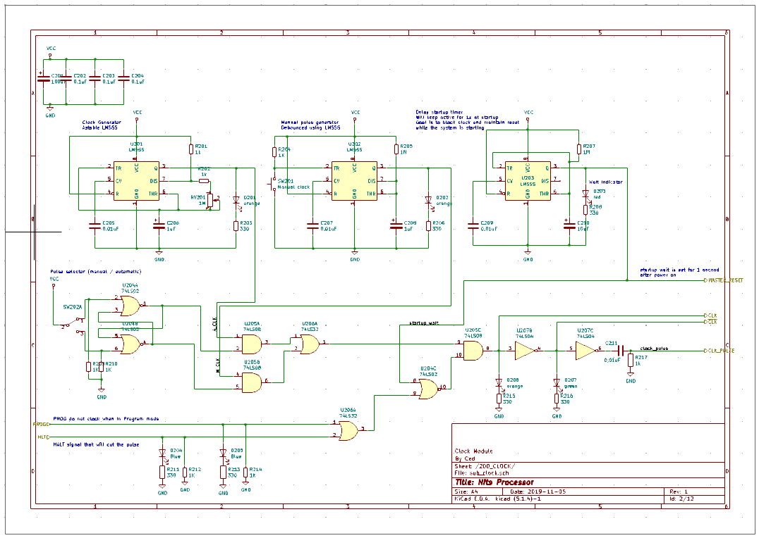
The clock module is actually more complex than one would expect.
The main features are:
- Provide a clean clock signal (square wave), an inverse clock signal (square wave) and a pulse signal (on rising edge of the clock signal)
- Offer variable clock speed (between 0,75Hz to 500Hz) in order to see what is happening
- Offer manual clock to ensure a step by step analysis
- Offer a startup delay (2s) to block clock signal and send master reset signal
The clock module has two switches:
- Manual / Automatic clock selector (choose between automatic pulse with variable speed and a manuel push button)
- Clock pushbutton
It has two input signals:
- HALT signal will stop the clock signal (either in manual or automatic mode).
- PROG signal will stop the clock signal (when programming the RAM, avoid having the CPU continuing it's job)
It has 4 output signals:
- CLK : the clock signal. A square wave. Frequency can vary
- INVERSE CLK : the inverse of the clock signal.
- PULSE : a pulse signal derived from the CLK signal
- MASTER_RESET : this signal sends a global reset to all computer parts at startup to make sure the system is ready to run
It is mainly built using 555 timers and some logic.
- A 555 timer in Astable mode will provide the automatic clock. The potentiometer changes the time value.
- Minimum value (when potentiometer is at 0ohm) : Period = 0,693 x (1kohm + 2 x 1kohm) x 1uF = 0,693 x (1000 + 2000) x 0,000 001 = 0,002079.s That is a frequency of 481Hz
- Maximum value (when potentiometer is at 1Mohm) : Period = 0,693 x (1kohm + 2 x 1Mohm) x 1uF = 0,693 x (1000 + 2 000 000) x 0,000 001 = 1,38s. That is a frequency of 0,72 Hz
- A 555 timer is monostable mode will provide the manual switch debouncing (to prevent bounce effect when switch is activated). When switching it will turn on the 555 time for a pre-defined period and it will turn off again, only once. The timer will stay on for a period defined by : period = 1,1 x 1Mohm x 1uF = 1,1 x 1 000 000 x 0,000 001 = 1,1s
- A 555 timer will provide the startup delay. When power is turned on, 555 is immediately set to on, until the capacitor is charged and then it turns off permanently. Period is defined using the same rule as the monostable above. Delay is 1s.
A few elements of logic are used to provide a clean signal and a debounced switch between the manual and automatic:
- Debouncing is performed using an SR latch with two NOR gates.
- Signal is output only if the following is TRUE : NOT (startup_wait | PROG | HALT)
- INVERTED CLOCK signal is provided using an inverter
- Pulse signal is provided using a RC with a time constant of period = 0,01uF x 1kOhm = 0,000 000 01 x 1000 = 0,000 01 s. Warning : the RC is positionned after a second inverter in order to buffer its effect and prevent poluting the clock signal. Also the double inverter gates provide a small delay compared to the actual rising edge of the clock signal.
Other chips used in this clock module:
- 74HCT02: provides four 2-input NOR gates
- 74HCT08: provides four 2-input AND gates
- 74HCT32: provdes four 2-input OR gates
- 74HCT04: provides six NOT gates (inverters)
Finally a few leds are positonned to show the actual status of each element:
- orange led show clock signal (automatic, manual, output)
- red led show the startup wait status
- blue led show action signals (HALT, PROG)
- green led show inverted clock signal

View of the prototype:

 Ced
Ced
Discussions
Become a Hackaday.io Member
Create an account to leave a comment. Already have an account? Log In.