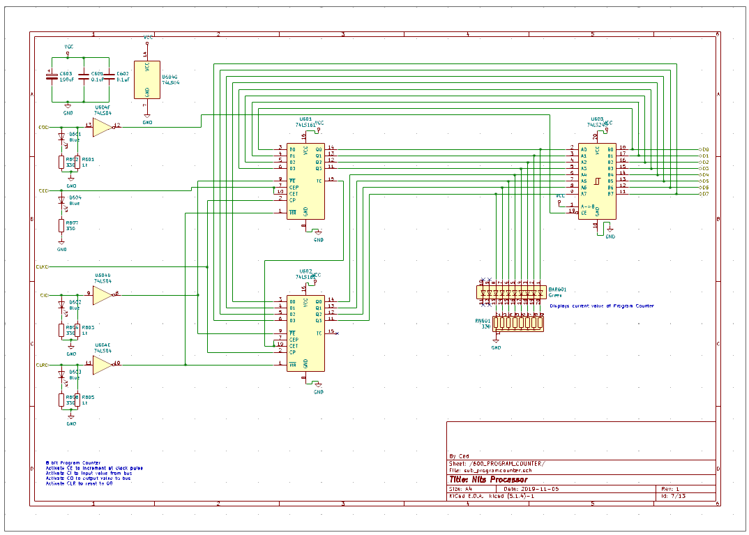
One register is very specific within the CPU: the Program Counter (PC).
Here is a definition of the Program Counter
So basically, if we read carefully the definition above, we understand that:
- A Program Counter is a register. It has the capability to store the information
- It has the capability to address the full scope of the memory that can store program (in some cases, program memory can be stored in a separate memory as data memory - otherwise it is shared memory and the PC can address the full scope of the memory). In our situation, it is shared memory and has 8-bit wide address.
- A Program Counter can be incremented (add 1 to the current value)
So for the Program Counter, there is need for a new action signal
- register_inc : this signal enables the automatic increment of the value of the register
The other action signals are the same as for a regular register:
- register_clear
- register_out
- register_in
[see log entry on Registers]
The IC used for our general purpose registers does not provide a way to increment the current value of the register. Increment could be implemented using gates but it is not such an easy task. Hopefully, there is an IC that provides just that:
- all the capabilities of a standard register (store, clear, input, output)
- a special signal to increment the value
However, the existing IC is 4 bits only, therefore we need to chain 2 ICs to provide an 8-bit register.
This IC is the 74HCT161:
- 4 bit inputs D0 to D3 (used to load the value of the register)
- 4 bit output Q0 to Q3
- 1 memory reset signal (master reset, this is an asynchronous signal in the 74161, synchronous in the 74163)
- 1 counter enable signal (synchronous, meaning that when active, the counter will be incremented at the next clock
- 1 clock signal (as usual the rising edge of the clock is used to synchronize the loading or the increment)
- 1 terminal count signal (this signal is used to chain 2 IC, when the 4 bit counter reaches the maximum value 1111, the TC signal is set to signal the next chip to increment)
- 1 parrallel in signal (this signal is used to load the value from the parrallel input)
When chaining two 74161, the TC signal is used to enable the counter of the next chip.
As for the general purpose register, the 74HCT245 is used as the 3-state output buffer.
As always, for learning purposes, the action signal are all set to active high and may need an inverter.

 Ced
Ced
Discussions
Become a Hackaday.io Member
Create an account to leave a comment. Already have an account? Log In.