-
Echo-in-a-box
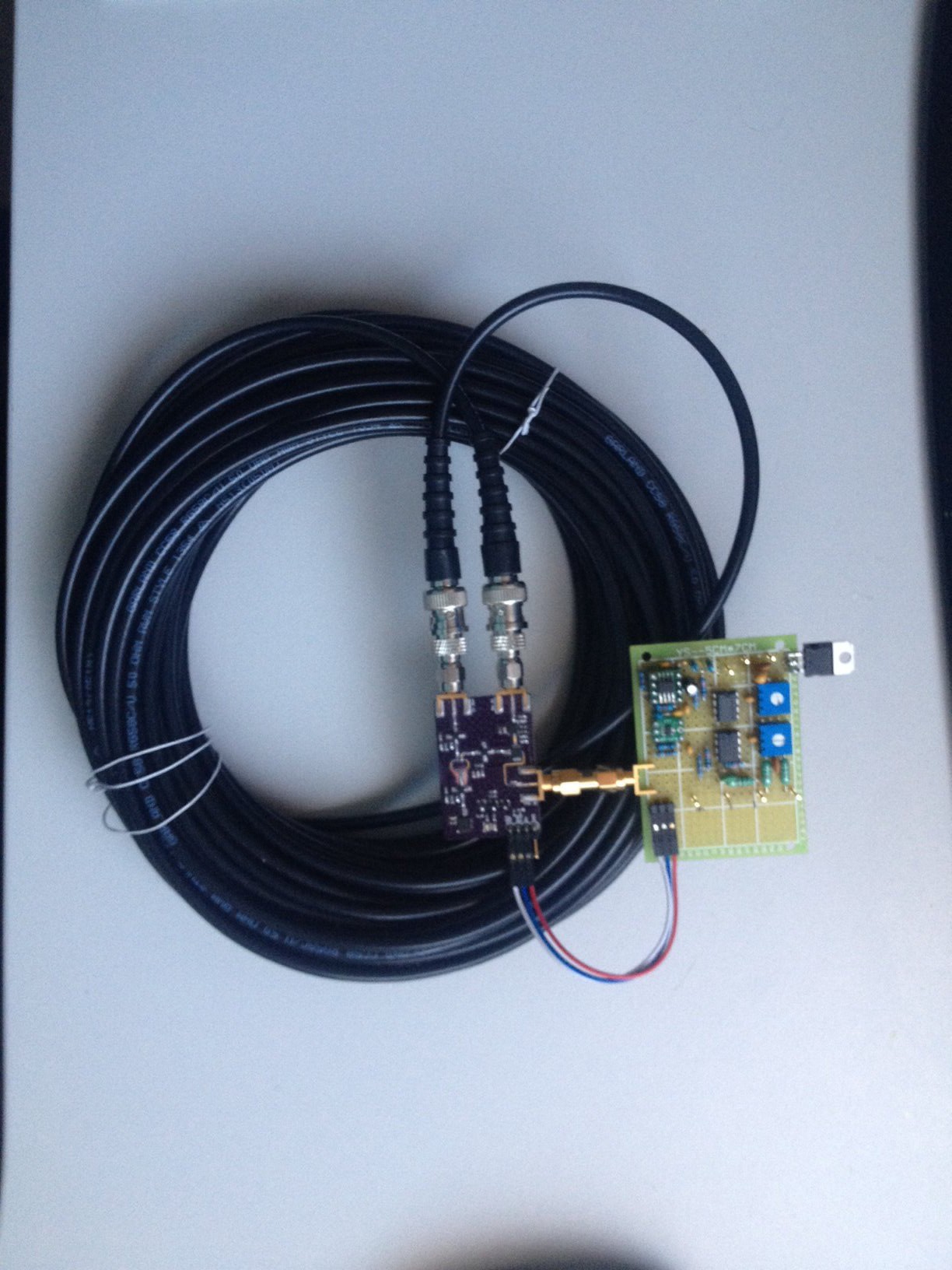
08/02/2014 at 23:30 • 0 commentsThis apparatus - basically just a long piece of coax cable - is used to emulate the radar echo over a longer range within the relatively small confines of the lab bench - mainly because it's cold and don't feel like taking all the apparatus outside.
![]()
20 meters of RG-58 coax will introduce a delay of about 100 ns. 20m of coax is equivalent to 30m of free space (because of the velocity factor of about 2/3), so the 20 meter cable is equivalent to a radar return from a target at a range of 15m.
The loss in 20m of RG-58 at 6 GHz is non-trivial, but then again the free-space path loss isn't trivial either - we expect substantial attenuation in either case.
At a triangle-wave modulation frequency of 25 Hz, the half-period (the length of the positive-gradient part of the ramp) is 20 ms, so if the VCO modulation range is say 200 MHz, we expect to see a frequency difference of (200 MHz * 100 ns / 20 * 10^6 ns) about 1 kHz, which is what we'll see in the echo signal on the output of the IF amplifier and filter chain.
-
A quick little video, and new IF filter/amp prototype
07/21/2014 at 11:34 • 0 commentsHere's a quick little video showing the current state of the prototype hardware.
I re-built another prototype of the IF filter/amplifier stage because I wasn't really happy with the previous one and wanted to make some design tweaks to get the best possible results using the component stock I had on hand. This one is a perf-board job since I wanted something to show relatively quickly before ordering more PCBs fabbed.
Now the IF filter/amplifier is working well, (tested up to 100 kHz with a function generator, with strong roll-off in the LPF as you go far above 25 kHz or so) along with the ramp generator, but I think there's a problem in the RF stage so unfortunately I can't show a fully working system delivering results at this time. And unfortunately, without a 6 GHz spectrum analyser, it's hard to show just the microwave VCO working, or something like that - it's really "all or nothing" in order to show the working results coming out of the mixer.
Thanks for following! :) -
Sweep generator redux
07/17/2014 at 07:32 • 0 commentsHere are some more notes concerning the sweep generator circuit that provides the modulation to the VCO, and some alternative circuits you may explore.
On my previous post on the sweep generator, Leo Liu pointed out to me that the XR2209, Exar's replacement for the XR2206 waveform generator, is still in production. This chip is potentially useful if you want to follow the MIT design as closely as possible for your basic FMCW radar project. The XR2209 is only an 8-pin package as opposed to 16 pins, but the internal architecture is pretty similar, just simplified a bit to reduce the pin count - read the datasheets and you should be able to port Charvat's XR2206 schematic across to the right pins on the XR2209 fairly easily, and you're also saving a bit of board space with the 8-pin chip.
Some of Liu's undergrad EE students at UC Davis have also recently been building some basic FMCW projects somewhat derived from or inspired by the MIT/Lincoln Lab work - and looking through their material I noticed they've recently been featured in a Hackaday post which you can see here. (Although to be slightly pedantic, personally I would have considered Tony Long's "RadarDuino" as the first radar system on an Arduino shield.)
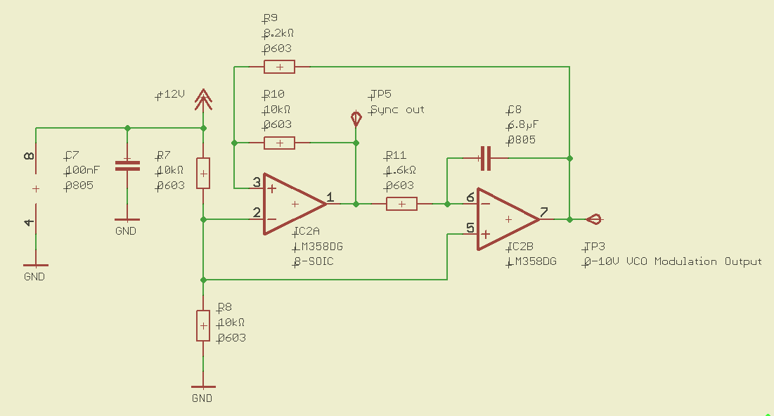
The schematic below shows another alternative circuit you may consider for a basic triangular sweep - just your classic Schmitt trigger integrator circuit to generate a triangle wave. This is a very simple low-cost circuit, using only about 50 cents worth of simple jellybean components you can get anywhere, which you've probably already got on hand at your home lab, school or hackerspace.
Another reason I like this approach is that I do sometimes like to encourage people to remember how to design and use real electronics to solve a problem, rather than the "MICROCONTROLLER ALL THE THINGS!" approach. Microcontrollers have their place, and can be really valuable in the right context - but for a lot of simple jobs, the "old" ways with fixed-function electronics can be simpler, easier and cheaper if you don't need the power and flexibility of a microcontroller. But sometimes the microcontroller kids these days don't grasp that - through no fault of their own, though, and perhaps more exposure to electronics outside of the microcontroller domain (and including the stuff that surrounds the microcontroller, in any microcontroller system) would help with that. Microcontrollers can be good, but just because you can use them for everything, doesn't mean you need to use them for everything or that you always should. (But if you're really itching to write some code and pump some SPI bytes, scroll down a bit.)When using a common, cheap opamp such as an LM358, one point to be aware of is that the output can't swing all the way up to the positive supply rail - it will be limited to a couple of volts less. One way to solve this is with a rail-to-rail opamp, but usually it's easy to avoid the problem without adding the cost of a rail-to-rail device - just power the opamp from a supply rail a couple of volts higher than the desired maximum output. Here I'm using a 12V supply. You don't need a bipolar power supply either - a single-sided supply works just fine.
You can probably add some tweaks to this circuit if you want - add a trimmer pot to this circuit for frequency adjustment, change the output amplitude if you're using an 0-5V VCO, etc. I'll leave that as a homework exercise for the reader. You can also take the square-wave output at the output of the first opamp, and use this to sync your PC software (or whatever data acquisition platform you're using) with the start of the sweep. Note that the start of the positive ramp (the minimum of the triangle wave) corresponds to the falling edge of the square wave, and also note that this is a 0-10V signal - you'll want to attenuate that before plugging it into a PC sound card.![]()
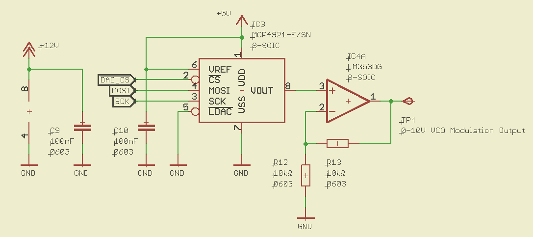
Another good option to consider is the use of a microcontroller (or PC)-controlled DAC which generates the modulation waveform. In this example I used a Microchip MCP4921 since that's what I had on hand, but there are many other candidates you could use. One of Microchip's 10-bit SPI ADCs might be a good low-cost choice - I really don't think you need 12 bits of resolution, and 10 should be more than sufficient for good performance.
An advantage of a microcontroller-based approach is that it gives you a great deal of flexibility to experiment with different modulation waveforms, different frequencies, different options you can easily select during operation etc - all under software control. The following is the basic circuit I used, just for demonstration purposes.![]()
If you wanted to be really fussy about the integrity and precision of the DAC output, a dedicated voltage reference may be used - but I didn't bother in this case, I just tied it to the 5V supply. Control of when the DAC latches isn't important here either, just tie the latch input to ground. Another jellybean LM358 (with 12V supply) was used to amplify the output to 0-10V, although if you're using an 0-5V VCO then just taking the DAC output (assuming a 5V reference) straight into the VCO should work fine. If you want to limit the sweep bandwidth to a fraction of the VCO's capability you can just do it in the software that controls the DAC.
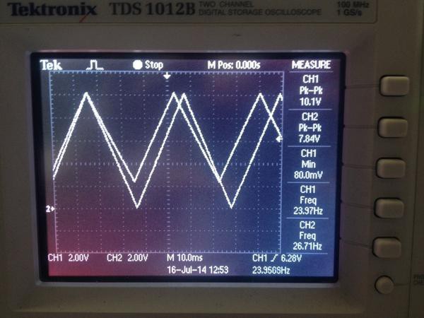
And the results look something like this:![]()
The amplified DAC output, on channel 1, nicely spans the full available VCO bandwith, across 0-10V, as well has having programmable waveform shape and frequency (subject to realistic limits - how fast can your microcontroller and your code pump out new updates into the DAC?), and it's quite a clean triangle wave. A nice result.
The smaller-amplitude signal on channel 2, which goes from an amplitude of about 2-10V, is the output from the very simple Schmitt trigger/integrator circuit shown above, using only a single LM358 and a couple of caps and resistors. This is also a pretty clean, undistorted triangular sweep - and this very low-cost circuit is probably sufficient for you to get a basic FMCW radar setup that is functional. Even though this circuit in its current form (something very crude I quickly threw together) doesn't access the full available bandwidth of the 0-10V VCO, you actually don't really need all that bandwidth.
If you want to use a microcontroller there are actually several other options you could try for digital-to-analog conversion without the performance of a dedicated serial DAC chip, saving a couple of dollars on your BOM. You could try an R-2R ladder DAC if you've got lots of microcontroller pins to spare - an old classic! Or you could try generating a waveform using high-speed PWM to generate a pulse train with varying duty cycle, and then filtering it. This is described in Atmel's AVR131 application note, for example. This approach means you're using only a single microcontroller pin and only a couple of jellybean components to make a simple RC low-pass filter plus an opamp as a voltage follower maybe (or for gain if you need 0-10V out), so the cost in terms of both microcontroller pin count and other components is very low, if your design already incorporates a microcontroller. I haven't tried this approach yet but I'll leave it as an exercise for the reader. -
Shiny tiny board
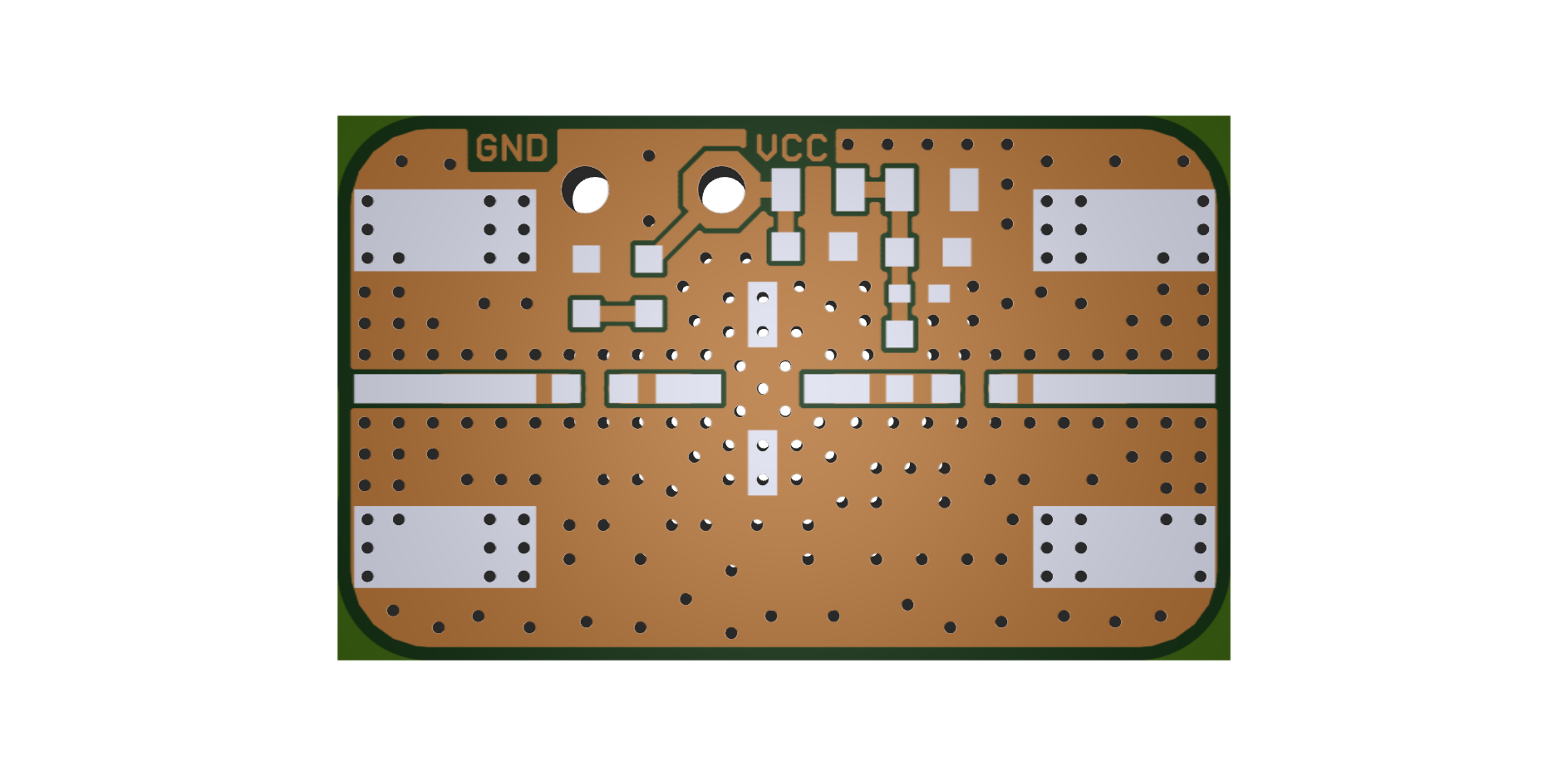
07/14/2014 at 11:57 • 0 commentsThis is another little board quickly whipped up today... a basic, general-purpose breakout board or building block for a SOT-86 "Micro-X" MMIC amplifier. You could use this with essentially any one, from many different manufacturers such as Hittite, MiniCircuits, RFMD, or others - just tweak the resistor value and other components to suit the device and the frequency you are using. To allow easy access to the ground plane for hacking, I'm going to try fabricating this with no soldermask or silkscreen at all, and well, mainly just to see what the product looks like - in practice with these components the soldermask won't be needed for viable component placement and soldering, and the end result should be very metallic and shiny.
![]()
-
Ramp generator
07/11/2014 at 20:29 • 1 commentHere's a quick update for today - the ramp generator / IF amplifier / filter / ADC board. This ramp generator design is just something whipped up really quickly that is essentially the same as Greg Charvat's MIT IAP 2011 design, using an Exar XR2206 to generate the triangle wave.
However, in a future iteration I'm planning to move to a different design - probably synthesis of the modulation waveform on a small microcontroller. The XR2206 is a very old chip, obsolete now, and it's hard to get. I've still got a few in stock, but it is not really a chip to use in a new design today in terms of openness, manufacturability, low cost, reproducibility and accessibility for other people around the world to be able to easily replicate the design.
I've modified the DC bias circuit on the output of the XR2206 to bias the output at about 5V DC, compared to +2.5V on Charvat's original schematic - this is because of the different VCO I'm using. The HMC431 wants a modulation voltage of 0-10V (across its full range) compared to 0.5-5.0V for the ZX95-2536C-S+. I will be running the VCO across about 60% of the full bandwidth at most using the current modulation circuit - not quite all the bandwidth is accessible before we start to get distortion of the ramp - which we do not want. But this possible bandwidth is plenty for our purposes.
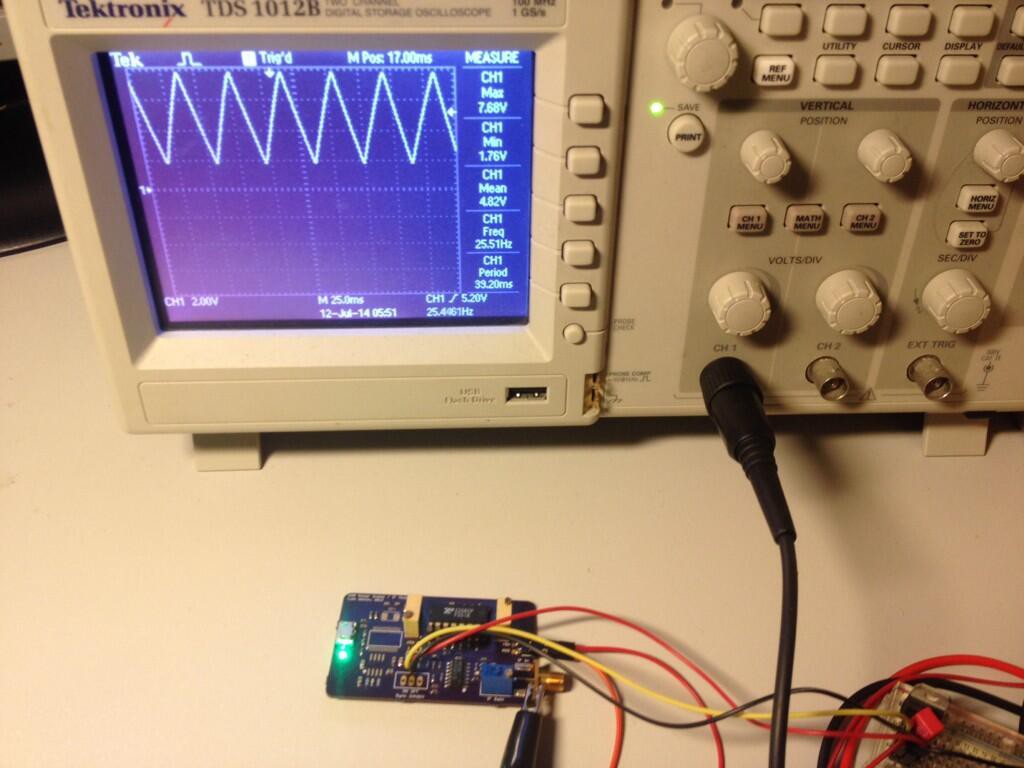
The yellow and red wires you can see tacked onto the board there are just a temporary +12V and +5V power supply, because I'm still missing a couple of power supply regulators needed to run the whole circuit off the USB port (USB connector visible at left.) This board also includes the IF amplification and processing components, but these haven't been tested yet. The IF input comes in from the RF mixer on the other board, into the SMA connector visible at right.![]()
-
Little building blocks
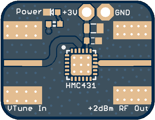
07/10/2014 at 19:59 • 0 commentsHere's another little board I quickly spun up and sent off to the fab tonight. It's just a really simple breakout board for the HMC431 VCO, which can just be used as a simple connectorised "building block" for rapid prototyping and quick, agile, flexible prototypes and experiments with further RF concepts I might play with in future.
I might also build similar building blocks such as MMIC amplifiers, mixer, LNA etc later. The key differentiating factor compared to existing connectorised modules and evaluation boards that you can get commercially from Hittite and Mini-Circuits etc is cost - they can be surprisingly high in price for what they are. For example the little Hittite HMC431 evaluation board costs 400 freaking dollars at Digi-Key - for a board essentially identical to the one shown below, with a $20 VCO chip and a pair of SMA connectors. And I think that huge difference in price is something valuable to address - but there is also merit in having a connectorised sub-board for each individual device, allowing re-usable prototyping of different designs, the agility to reconfigure new experiments, etc.
I'll just be using cheap, standard FR-4 instead of specialized RF substrates, but the RF loss in the dielectric isn't likely to be a huge dealbreaker.![]()
-
Pic
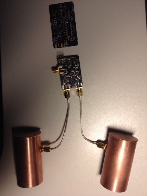
07/09/2014 at 17:34 • 0 commentsHere we see the completed pair of prototype antennas, RF board, and IF amp / sweep generator board (not assembled yet)
I will have to do some serious fixing to the RF board before powering it up though... if I turn it on at the moment it will be driving about 6 dBm into the TX antenna drive amp and the mixer LO drive amp, and that'll kill them... I forgot to put the attenuators in. -
Open-source Goodness
07/07/2014 at 13:24 • 0 commentsI've just been updating the git repository with the source files, schematic, and Gerber files for the current version of the RF board. So you can go and check it out! Feel free to let me know what you think... any ideas or comments. :)
And just to flesh out this post a bit, here's a picture.
![]()
-
The Fine Print
07/07/2014 at 09:46 • 1 commentIt's worth reading the actual terms and conditions closely for the Hackday Prize contest.
"The project must be a connected device (i.e., transmits information through the Internet)."
"Is the entry a connected device and is that “connectedness” meaningful to the function?"
So, we're only looking for projects that are Internet-connected systems that are transmitting information over the Internet?
That's a little bit of a shame, and excludes many great projects I've seen around here.
Of course, it's possible to "loophole" just about any device or system you might build and add some Internet connectivity - but it would be kind of pointless, and not meaningful to the function and use context that the system was originally designed for - so while you could pass the "must be a connected device" criteria, you would fail the "connectivity meaningful to the function" criteria. Although the latter is just a judging factor and not a strict criterion.
I would like to see this rule be re-written, personally. However, for me personally, I don't care about the prize really, and will continue to publish this project here anyway.
I also have to laugh a little at the "participants acknowledge that commercial space travel, while currently in development, may not be available to consumers by November 14, 2017. Redemption of this prize is subject to availability" clause in the rules.
YOU WILL WIN A TRIP TO SPAAAACEEEEE!!!! (if you can actually get access to any commercial "space tourism" within the next few years, which you presently can't and probably won't be able to within the next few years, and if it is available within the prize budget, and if you're medically qualified for a spaceflight.) It would be more sensible to just advertise it as a cash prize IMO. -
How much does it cost?
07/02/2014 at 06:00 • 0 commentsBased on my current design iteration for the RF board, the bill of materials consists of 1x HMC431LP4E VCO, 1x HMC717LP3E LNA, 1x HMC219AMS8E mixer, 3x HMC476MP86E gain blocks and 3x SMA connectors (Molex 0732511150). At single-unit quantities from Digi-Key, those will cost you about USD $60 in total. I have excluded a few parts, such as the passive capacitors and resistors, but they're quite inexpensive and this is just a very quick budget estimate. Obviously the IF signal processing components are all excluded too, but the RF parts account for the majority of the cost.
When we consider that something like the Mini-Circuits ZX05-43MH-S+ mixer specified in Greg Charvat's 2011 MIT IAP radar project (a major source of inspiration for this project) will cost over $40 alone (and the VCO, each gain block, and the LNA each cost approximately that much again) it is clear that my objective of a substantial cost reduction (compared to Charvat's design for his students' projects as the "reference design") has been achieved.
Simple, low-cost FMCW radar
A basic radar system makes radar accessible at low cost for experiments with rangefinding & navigation of autonomous aircraft or spacecraft.
