As explained in previous logs, the MCU is the brain of the board. It configures the HDMI bridge chip, and handles power-sequencing of the display.
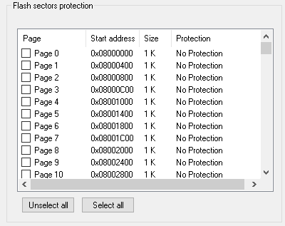
Out of curiousity, I connected an STLink to the SWD pads on the PCB, and behold, the chip is unlocked!

This allowed me to extract the firmware. I plan to reverse-engineer the firmware to determine how it configures the system, and how it could be configured via USB.
GPIO map:
| Label | MCU Pin | MCU Port | Net Name | Supply Voltage |
| E1 | 31 | PA10 | VDD_HDMI | 1.1v |
| E2 | 14 | PA4 | VDD_MIPI | 1.2v |
| E3 | 11 | PA1 | VDD33_HDMI VDDIO33 | 3.3v |
| E4 | 30 | PA9 | VDD_DISP_18 | 1.8v |
| E5 | 42 | PB6 | VDD_BL (V3) | ? |
| E6 | 13 | PA3 | VDD_DISP_33 | 3.3v |
| E7 | 17 | PA7 | VDD_OLED (V1/V2) | +V/-V? |
| E8 | 43 | PB7 | VDD_BL (V3) | ? |
| E9 | 45 | PB8 | Feedback? | ? |
| E10 | 29 | PA8 | VDD_OLED (V1/V2) | +V/-V? |
| L1 | 16 | PA6 | LED1 | |
| L2 | 15 | PA5 | LED2 | |
| A | 21 | PB10 | IOA (1.8v) | |
| B | 46 | PB9 | IOB (1.8v) | |
| C | 25 | PB12 | IOC (3.3v) | |
| D | 22 | PB11 | IOD (3.3v) | |
| B1 | 28 | PB15 | BTN1 (Left) | |
| B2 | 27 | PB14 | BTN2 (Right) | |
(Ignore the labels column - I am using it within my reverse engineering to track the signals)
Flash Layout
| 0000 0000 | Boot Space (Aliases to one of the below regions) |
| 0800 0000 | Flash space |
| 1FFF F000 | System memory space |
| 2000 0000 | SRAM space |
| 1FFF F7D6 | USART Bootloader |
 Jared Sanson
Discussions
Become a Hackaday.io Member
Create an account to leave a comment. Already have an account? Log In.
Actually I found you can just press the button closest to the DSI connector while plugging the USB, and the MCU will enter DFU mode, from which you can upload and download firmware. Mine wasn't read protected either, so I was able to backup the original firmware.
However it looks like the I2C bus is connected to pins 40 and 41 of the MCU, which are not muxltiplexed to the I2C module, so I'm wondering if they are bitbanging the bus .. will have to get a closer look with an oscilloscope.
Are you sure? yes | no
Yup. Took a quick look at the hex file. Couldn't identify the use of the "real" I2C Peripheral Registers...
Are you sure? yes | no
Hi Jared,
I have a 4k MIPI board and tried connecting to it through ST-Link but wasn't able to access / read . SWD Pads were connected in following order:
Pad-1: 3.3v, Pad-2: GND, Pad-3: SWDIO, Pad-4: SWCLK.
Error: Target Detection Failed.
Any idea what I may be missing here?
Are you sure? yes | no
Hi Jared,
Thank you for your reply. I found them.
Regarding the chip unlock, you have said "I connected an STLink to the SWD pads on the PCB, and behold, the chip is unlocked!"
Which STLink model you've used? Does this model work?
https://www.amazon.ca/STLINK-V3SET-Modular-debugger-Programmer-STM32/dp/B07MB9TKDX/ref=sr_1_fkmr0_1?keywords=STLINK+Modular+in-Circuit+debugger+and+Programmer+for+STM32&qid=1580932804&sr=8-1-fkmr0
Can you please introduce your STLink that was functional on this board?
Thanks and regards,
Daryon
Are you sure? yes | no
I'm just using the STLink built into my STM32Discovery board, not a standalone programmer. I'm not an expert on STM32 but I think almost any STLink should work on this chip, so just get the cheapest one you can find. You definitely don't need to spend $90 on one :)
Are you sure? yes | no
Hi Jared,
Thanks for the nice job! I followed your post and got stuck here! How can we access to the firmware uploaded to the chip?
Thanks and regards,
Daryon
Are you sure? yes | no
Hi, you can find the firmware dumps under 'Files' on the main project page. No guarantee this is a complete dump...
https://hackaday.io/project/168212-mipi-hdmi-bridge-re#menu-files
Are you sure? yes | no
Looks good, though. Ran it through Ghidra (Little Endian, Cortex, Thumb), gives a nice disassembly.
Are you sure? yes | no