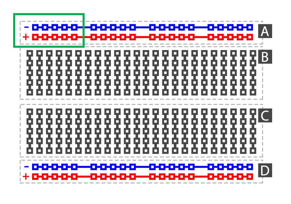
At around 3:15 in the video (https://youtu.be/SAgiv4o8rxQ) you can see I'm installing a little part next to the Arduino Uno. This is a homemade voltage distributor. It's sole purpose is to distribute 5V and 0V to other components. I made it using some double sided prototype board and soldering some 2.54mm female header pins on it. All the 5V pins are soldered together and all the 0V pins are soldered together, just like the + and - strips on a breadbord (see green box on picture below). Hope this cleared it out for some people.
Double sided prototype boards: https://www.banggood.com/Geekcreit-40pcs-FR-4-2_54mm-Double-Side-Prototype-PCB-Printed-Circuit-Board-p-995732.html?p=E01411629100201406T1&custlinkid=669188
2.54mm female header pins: https://www.banggood.com/10pcs-40Pin-2_54mm-Female-Header-Connector-Socket-For-DIY-Arduino-p-945516.html?rmmds=search&cur_warehouse=CN

 Brian Brocken
Discussions
Become a Hackaday.io Member
Create an account to leave a comment. Already have an account? Log In.