 Alastair Young
I made a new test jig to replicate the function of the old one - a much tidier build this time. It is again configured as an Arduino shield so I can swap it onto the same Arduino without reprogramming. I used one of the scrap OshPark boards for the top level guide, skimming all the copper off in the mill first. The OshPark board holes are much more snug on the pogo pins - I actually have to ream them out with the drill. The PCBWay holes are loose. I don't have any gauge pins so I can't tell who is off. Both work though - header pin holes are not that critical.
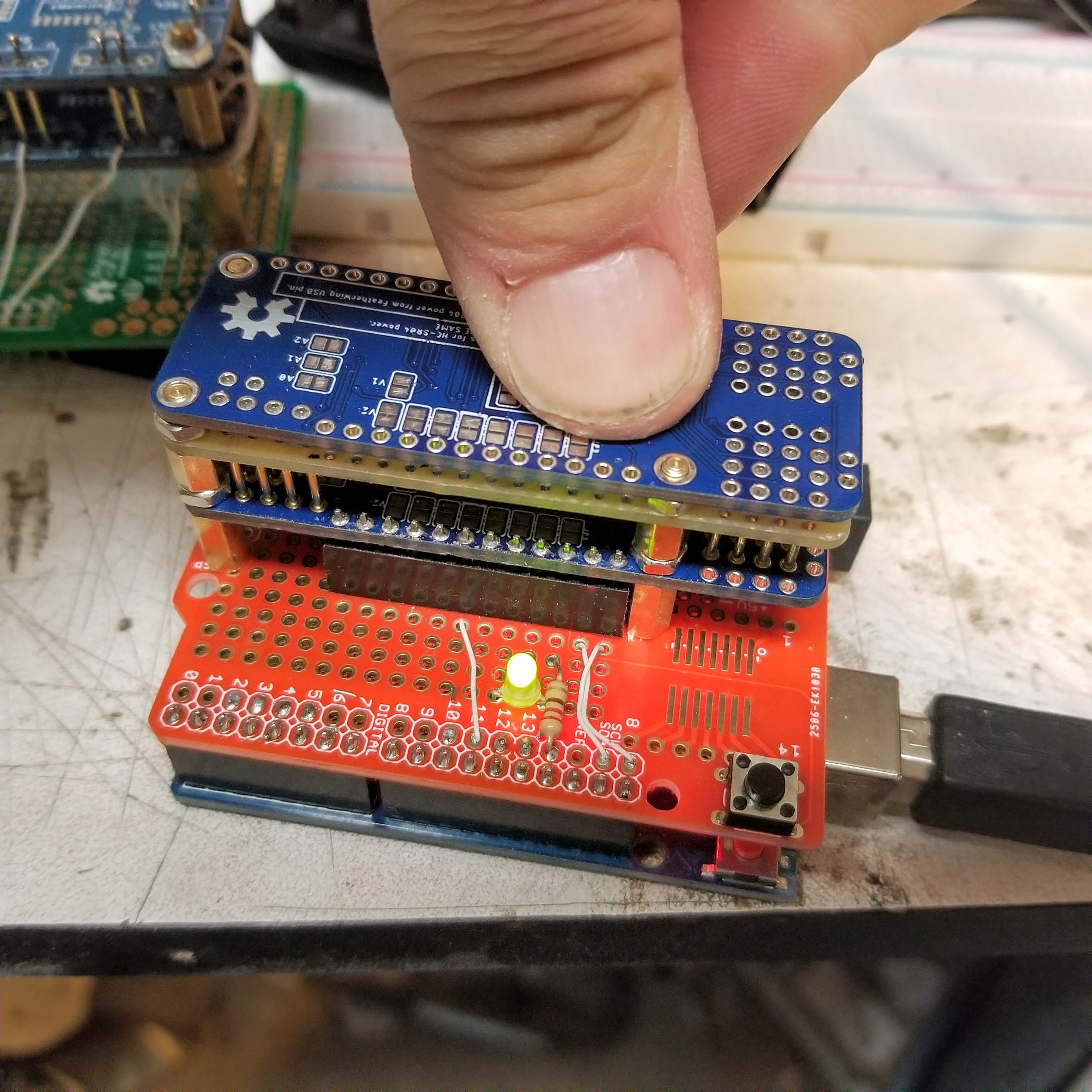
I am using a PCBWay board for the main part of the jig, with a PCF8574 at 0x20 talking to the Trig pins and the Echo pins wired back to spare Feather pins from the 74HC125 pads (chips not installed). Pogo pins are on the trig, echo and non-feather control pins with the regilar parallel feather pins connected down to the protoshield with pluggable headers. The pogo pins are only soldered on the bottom and have no wires directly attached. The jig is configured upside down so all the wiring is exposed when it unplgs - this should make the whole thing easier to maintain, as kynar wire and pogo pins are a bit fragile.
I made up one board by hand - tested good first time :-)
I'll make up a production batch next weekend - I need to stock reset switches.
Discussions
Become a Hackaday.io Member
Create an account to leave a comment. Already have an account? Log In.