 Alastair Young
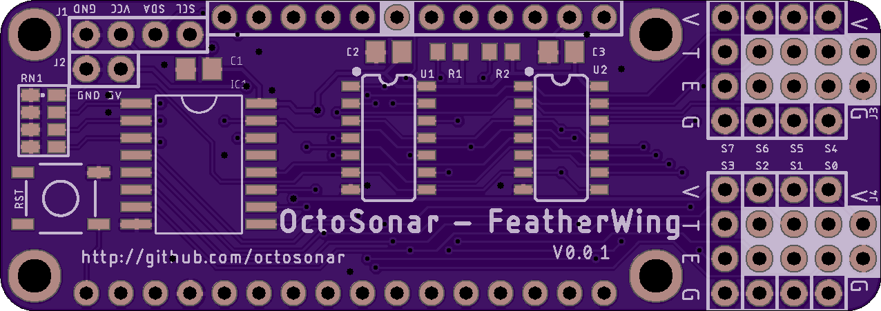
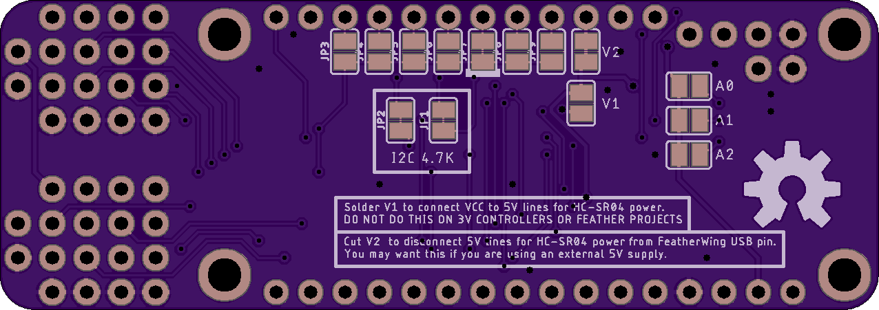
Initial design done. I originally went with one sensor connector block in an extension on each end, but then realized if used as an under-wing the wires would clash with the USB, so I packed them both into an extension at the right hand end. This made the routing a lot more challenging hauling 16 data lines back from one end.
Went with 6mil for data a 10mil for power, with 0.35mm and 0.5mm vias respectively with 6 mil annular ring. Previously I've always done 8mil traces, but this lets me space lines at 25mil
The board maintains the capability of use as a standalone board for use with non-feather projects - so it can replace the existing unit in stock. It has a reset button and defaults to "GPIO-11" which is Arduino pin 2 on the Feather 328P (on order).
Now for the X2....
Discussions
Become a Hackaday.io Member
Create an account to leave a comment. Already have an account? Log In.