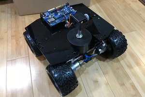
Owen
OwenFeatures:
- Makes a great platform for further development or as a teaching aid, has ready-to-go software that should inspire and invite discussion. Easy to obtain components.
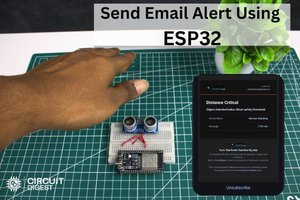
- Lidar demo! the UI can be served directly onto a mobile phone attached to the unit as a access point. The interface was designed with phone displays in mind, though it works well on any HTML5 browser.
- Even without a servo the UI gives a nice clear distance display, with a history graph, and all the main sensor setting available.
- With a servo attached you get extra controls for manual motor movement, scanning, zeroing, and a simple graphical polar plot of the readings to emulate a 'real' LIDAR.
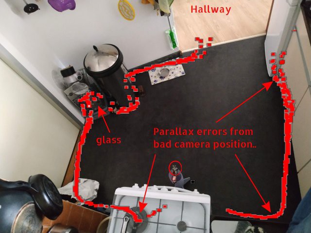
- Up to 4M range (in ideal conditions, in reality 2m is a good maximum to plan for), the range readings tend to continuously float by a few CM, but this is acceptable for my uses.
Featurettes:
- Auto scan function has wide and narrow ranges, and the step resolution can be adjusted.
- Meaningful options for setting the speed and range values of the sensor, and the ability to narrow the field of view (Region of Interest), improving sharpness at the expense of range.
- WiFi can be configured to work as a standalone AccessPoint, or connect to an existing network.
- The demo software is not particularly convoluted; I'm not a 'programmers' programmer, so I tend to keep routines simple and comments long.
- The coding effort on this is a mix of C for the ESP32 code; plus a bunch of JavaScript in the IDE page that interacts with the ESP32 over a simple REST api to trigger and update the readings, draw graphs, trigger sensor and scan modes, etc.
- The motor can be de-powered remotely, useful to save power and reduce heat (the motor can get quite warm)
Assembly:
See the instructions section below.
Also look at the README in the GitHub repo for this project, or the files section below.
Feel free to make your own base from Lego, clay, toilet rolls and duct tape, or whatever floats your boat, I provide a 3D model to print too.
Notes for other IOT Ecosystems
I see no reason why this would not work with an ESP8266, or other Wifi-enabled Arduino-alike boards. The WiFi and Sensor libraries are very standard, you would have to check wiring etc but the code and design are pretty MCU independent.
Issues:
- The code can be a bit laggy/unresponsive to control button presses,
This is dependent on network congestion and sensor measurement interval.
It's caused by the I2C access to the sensor and motor movements blocking the WiFi server in the ESP. For the same reason movement during scans can also be jerky since they are dependent on the client requests. being processed - Currently there is no Homing/Zero sensor. You need to 'zero' the sensor rotation before power up (or while the servo is de-powered).
- There is no facility for continuous sensor rotation in this version, I assume the sensor is directly wired and that the user will ensure it is 'homed' before use. The software limits movement to +/- 145g degrees from that.
- Lockups and WiFi disconnects associated with motor movement are likely caused by the USB supply dipping and causing brownouts, use a decent PSU and cable.
Future:
The UI lagginess needs solving with a software re-architect to use both cores. One for sensor//motor, the other for webserver, allowing the I2C and Wifi activities to co-exist without blocking each other.
The SparkFun library used for the sensor could be replaced with the genuine ST Micro one,
Thoughts:
Lots can be done in software, both to improve response, but also:
- Calibration: The VL53L1X has calibration modes for distance offset, signal level and temperature compensation. None of these are currently implemented, but could be useful.
- Output; a much bigger scan graph, with scales and other visual aids.
- DataLogging; with the PSRam on the ESP32 boards it should be possible to log scan results for later access.
 ElectroScope Archive
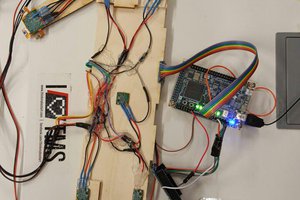
 Simon Trendel
 blinknbuild