 Chris.deerleg
For establishing a connection to the PCB are following steps required:
- Connect ST-Link to PCB
- Remove the write protection (not sure if required)
- modify Arduino IDE
- reduce flash speed
- create a board variant
- add a board in Arduino IDE
- reduce flash speed
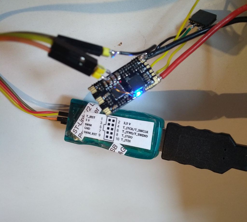
On the image above is a picture of the ST-Link programmer connected to the PCB. The ST Link programmer pin "T_SWSCLK" is connected to testpoint which is marked as "DIO" and "T_SWDIO" is connected to testpoint which is marked as "CLK". If the pin are interchanged, it will not be possible to get a connection to the PCB.
As Next remove the write protection.
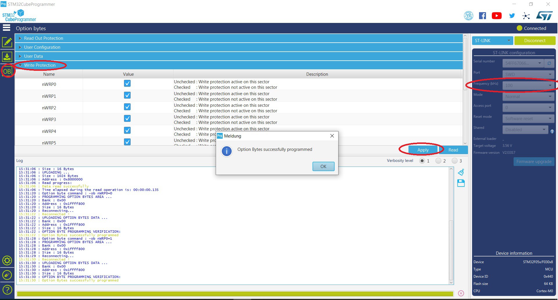
Above is the STM32 cube programmer shown. The tool is available on the STMicroelectronics home page. After the successful installation it should be possible to establish and connection to the PCB. The default communication frequency of 4000 kHz don't work for me. I used 100 kHz as frequency to get a stable connection. In the OB menu under sub-menu "Write Protection" tick all boxes and apply. Once done the write protection is successfully removed.
 To run a blink sketch the following is to do.
- reduce the flash frequency
- create a board variant
- add a board in Arduino IDE
Reduce the flash frequency
the following show how to change the programmer frequency in a Arduino IDE with a STM32F.
..\ArduinoData\packages\STM32\tools\STM32Tools\1.3.1\tools\win
in the Arduino path shown above is the stm32CubeProg.bat to modify.
:prog
%STM32CP_CLI% -c port=%PORT% %MODE% %ERASE% -q -d %FILEPATH% %ADDRESS% %OPTS%
exit 0
:prog
%STM32CP_CLI% -c port=%PORT% freq=480 reset=SWrst %MODE% %ERASE% -q -d %FILEPATH% %ADDRESS% -v %OPTS%
exit 0
at the end of the stm32CubeProg.bat add "freq=480 reset=SWrst" to reduce the frequency and change to software reset. Further add "-v" to verify the code after flashing.
Create a board variant
The following shows how to create a own board variant for the Arduino IDE.
..ArduinoData\packages\STM32\hardware\stm32\1.7.0\variants
in the folder variants (path above) are all board listed which are usable in the Arduino IDE .

to create a new board variant for the HiCuDriver copy the DISCO_F030R8 folder and renamed it to HiCuDriver_Dshot.
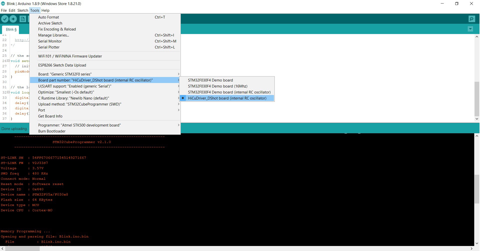
Add a board in Arduino IDE menu
the following shows how to add the own board variant to the tool menu in the Arduino IDE.
...ArduinoData\packages\STM32\hardware\stm32\1.7.0
it is necessary to change the "boards.txt" which is to find in the path shown above. add the lines of "# HiCuDriver_DShot" in the section "# Generic F0". Further details see below.
###############################
# Generic F0
GenF0.name=Generic STM32F0 series

GenF0.build.core=arduino
GenF0.build.board=GenF0
GenF0.build.mcu=cortex-m0
GenF0.build.series=STM32F0xx
GenF0.build.cmsis_lib_gcc=arm_cortexM0l_math
GenF0.build.extra_flags=-D{build.product_line} {build.xSerial}

....

# DEMO_F030F4_HSI board
GenF0.menu.pnum.DEMO_F030F4_HSI=STM32F030F4 Demo board (internal RC oscillator)
....

# HiCuDriver_DShot
GenF0.menu.pnum.HiCuDriver_DShot_HSI=HiCuDriver_DShot board (internal RC oscillator)
Disco.menu.pnum.HiCuDriver_DShot.node="No_mass_storage_for_this_board_Use_STLink_upload_method"
GenF0.menu.pnum.HiCuDriver_DShot_HSI.upload.maximum_data_size=4096
GenF0.menu.pnum.HiCuDriver_DShot_HSI.upload.maximum_size=65536
GenF0.menu.pnum.HiCuDriver_DShot.build.mcu=cortex-m0
GenF0.menu.pnum.HiCuDriver_DShot_HSI.build.board=HiCuDriver_DShot
GenF0.menu.pnum.HiCuDriver_DShot_HSI.build.product_line=STM32F051x8
GenF0.menu.pnum.HiCuDriver_DShot_HSI.build.variant=HiCuDriver_DShot
The led is connected to pin PB3. Therefore to get a blinking led, replace "LED_BUILTIN" with "PB3"
// the setup function runs once when you press reset or power the board
void setup() {
  // initialize digital pin LED_BUILTIN as an output.
  pinMode(PB3, OUTPUT);
}

// the loop function runs over and over again forever
void loop() {
  digitalWrite(PB3, HIGH);   // turn the LED on (HIGH is the voltage level)
  delay(250);                       // wait for a second
  digitalWrite(PB3, LOW);    // turn the LED off by making the voltage LOW
  delay(250);                       // wait for a second
}
Discussions
Become a Hackaday.io Member
Create an account to leave a comment. Already have an account? Log In.