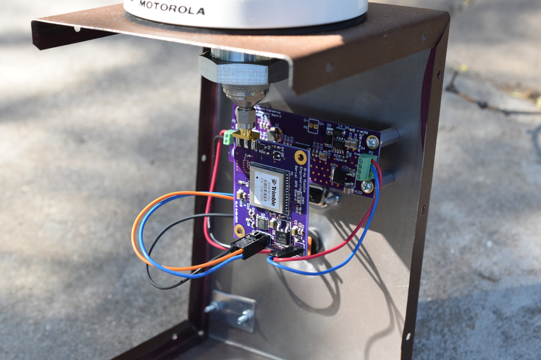
Here are the internals of the project.

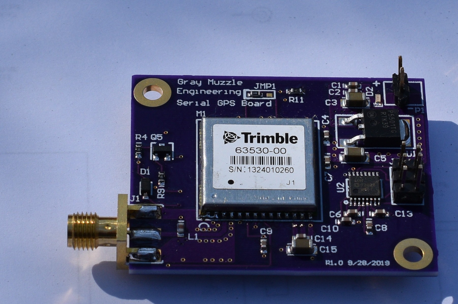
The PCB for the GPS module is the only completely new major part used. Back in 2012, I was working with the Beaglebone, developing a GPS, IMU and RC Servo interface cape. The Cape went through several iterations as I added stuff and fixed issues. Trimble Copernicus II modules were readily available, so I used them. After the Beaglebone went through multiple versions of it's peripheral access system, I punted the Beaglebone, rather than spend more time chasing their software iterations. In the course of the project, I wrote a number of utilities to support the Copernicus modules and successfully got the NTPD program to work with it. Fast forward to this summer, I was able to unsolder the Copernicus modules from the old prototype boards without damage, so I had a few on hand. This was enough motivation to stick with the Copernicus module. The Copernicus modules are still available from Sparkfun, but If I had to buy a module, I would probably buy something a lot more modern that understands Glonass and others.

The antenna connector is also re-used from the Cape project. Power for active antennas and sensing the status of the antenna require a handful of passive components visible on the left side of the board. A point of load LDO regulator is in the upper right corner of the board and the logic level to RS232 level shifter and connector is below the regulator. The jumper JMP1 allows selecting the 1PPS signal, or a second UART channel in a Trimble proprietary format for routing through the level shifter. NMEA formatted data is always available.

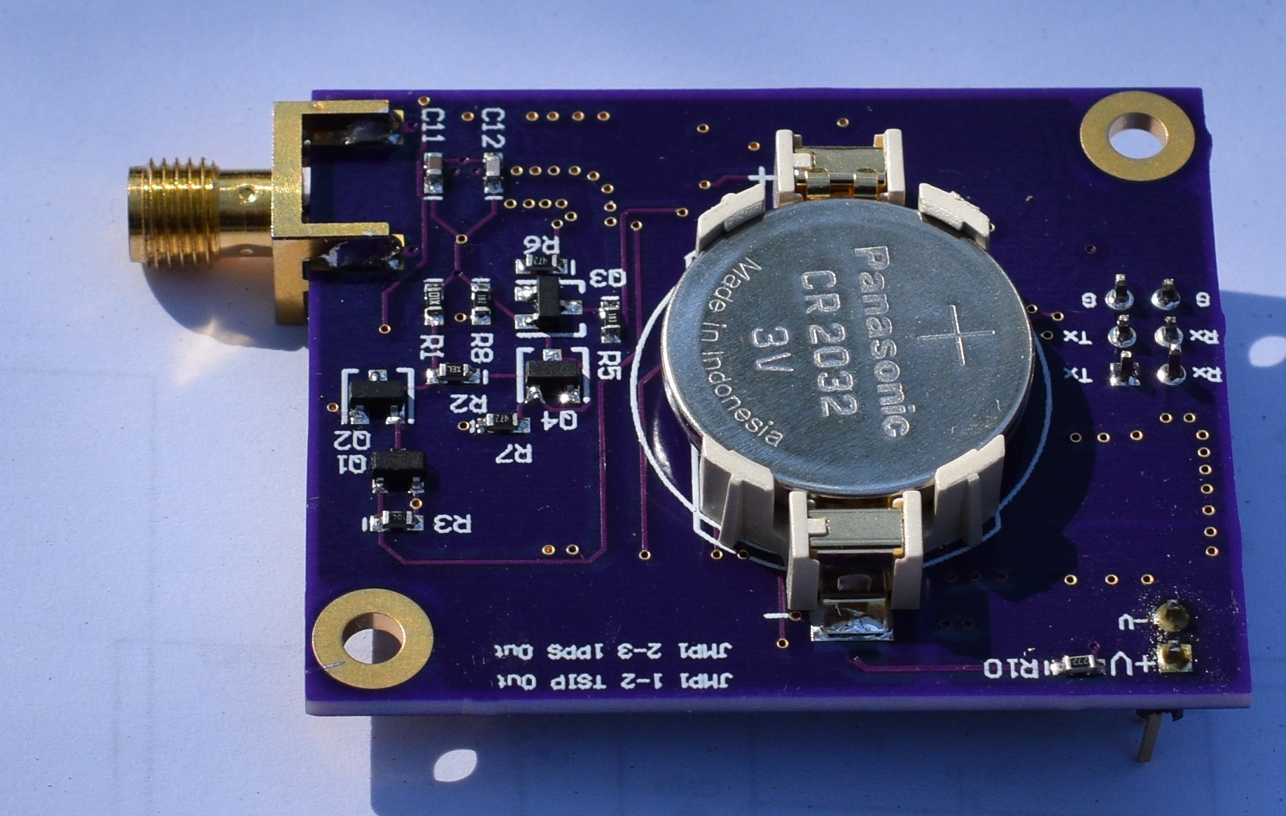
A coin cell to provide power for data retention is on the back side of the board, along with more parts for the antenna power circuit.

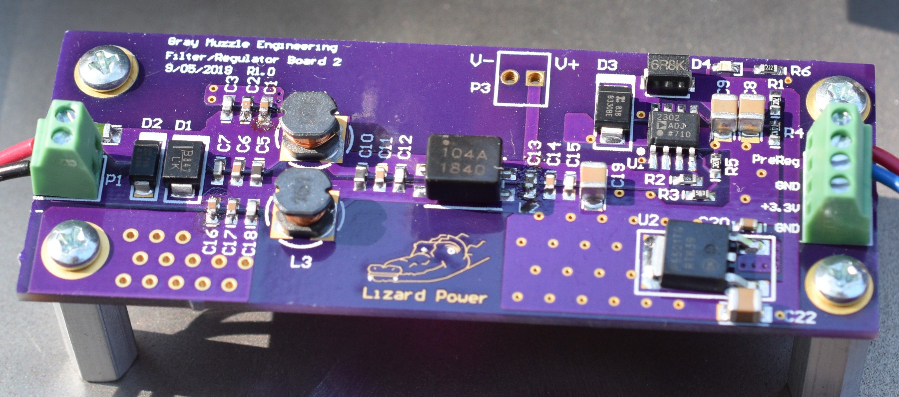
The power filter / regulator board is an extra from my Geiger Counter project. A switching regulator puts out +5V and the LDO below it puts out +3.3V. The 3.3V is not used on this project, as there is already one on the GPS board. Initially, I had not planned to use the filter / regulator board, but the LDO on the GPS board ran hotter than I liked with 12V in, and I wanted some filtering, so I added the board.
The enclosure was folded up from 0.030" steel that was left over from a mechanical project. It is powder coated for the finish.
Lately, a lot of my projects are re-using stuff from previous projects, and building small modules to increment the functionality. I like this method because it allows me to iterate individual sections cheaply if I want to improve or fix an issue. It also lets me re-use spare boards to reduce costs of a project.
 Bharbour