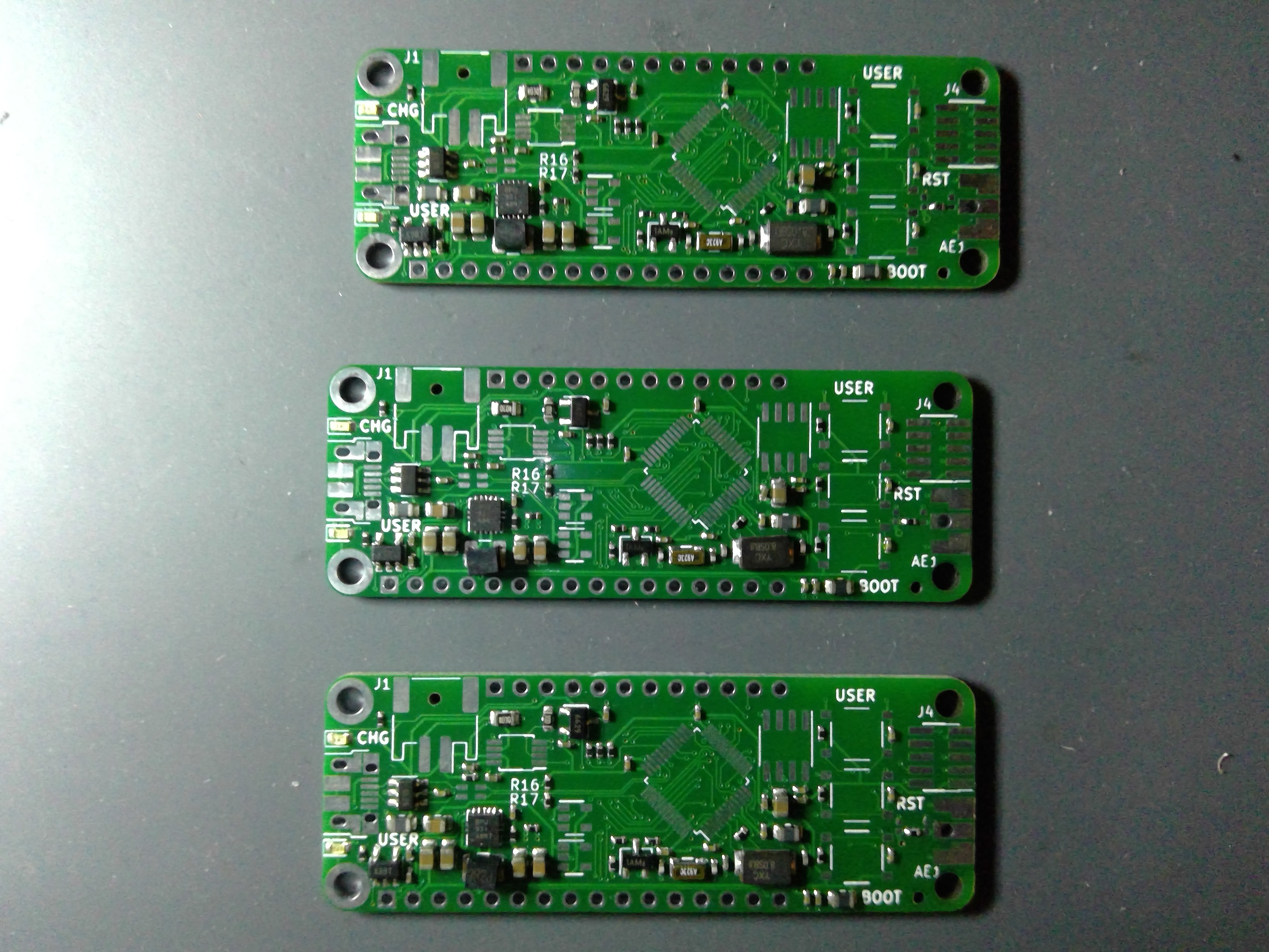
Update on the project after the holiday! I got in the semi-assembled boards from JLCPCB. I'm very happy with the quality and speed of the assembly process. The boards look great:
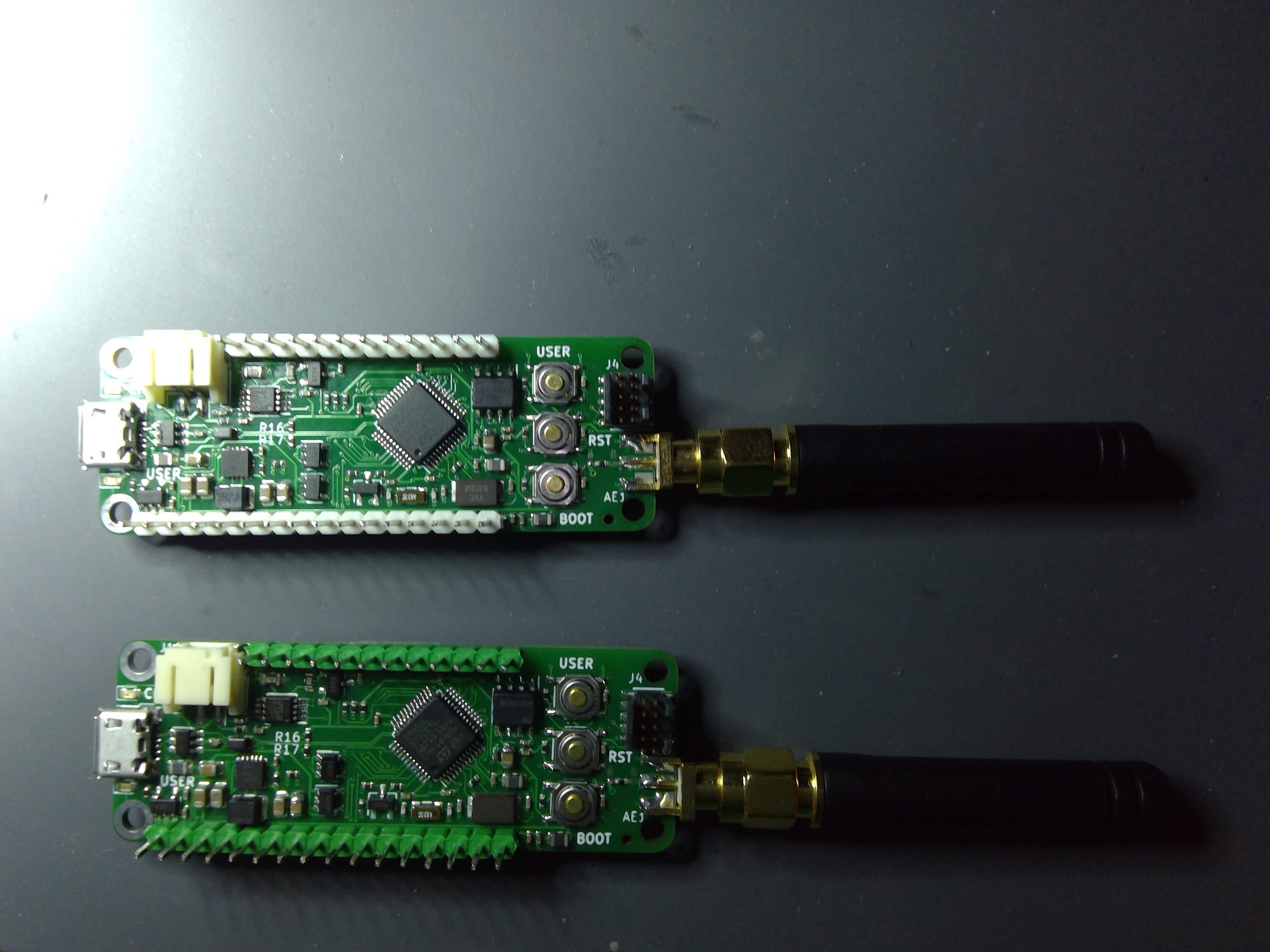
 Sorry for my crappy photography skills. JLC doesn't have any connectors in their SMT assembly library which is strange, so they aren't assembled. The three user buttons were supposed to be assembled, but that was an error on my part. I did not select a part on the BOM selection step of the process. Oh well, Digikey to the rescue. The rest of the parts were either not in stock or not available for assembly. Time to get out my iron!

I decided to start with two so that I can run the LoRaWAN stack's ping pong application as a test as well as get them connected to my Raspbery Pi based LoRaWAN gateway for testing. However, some initial testing is in order first!
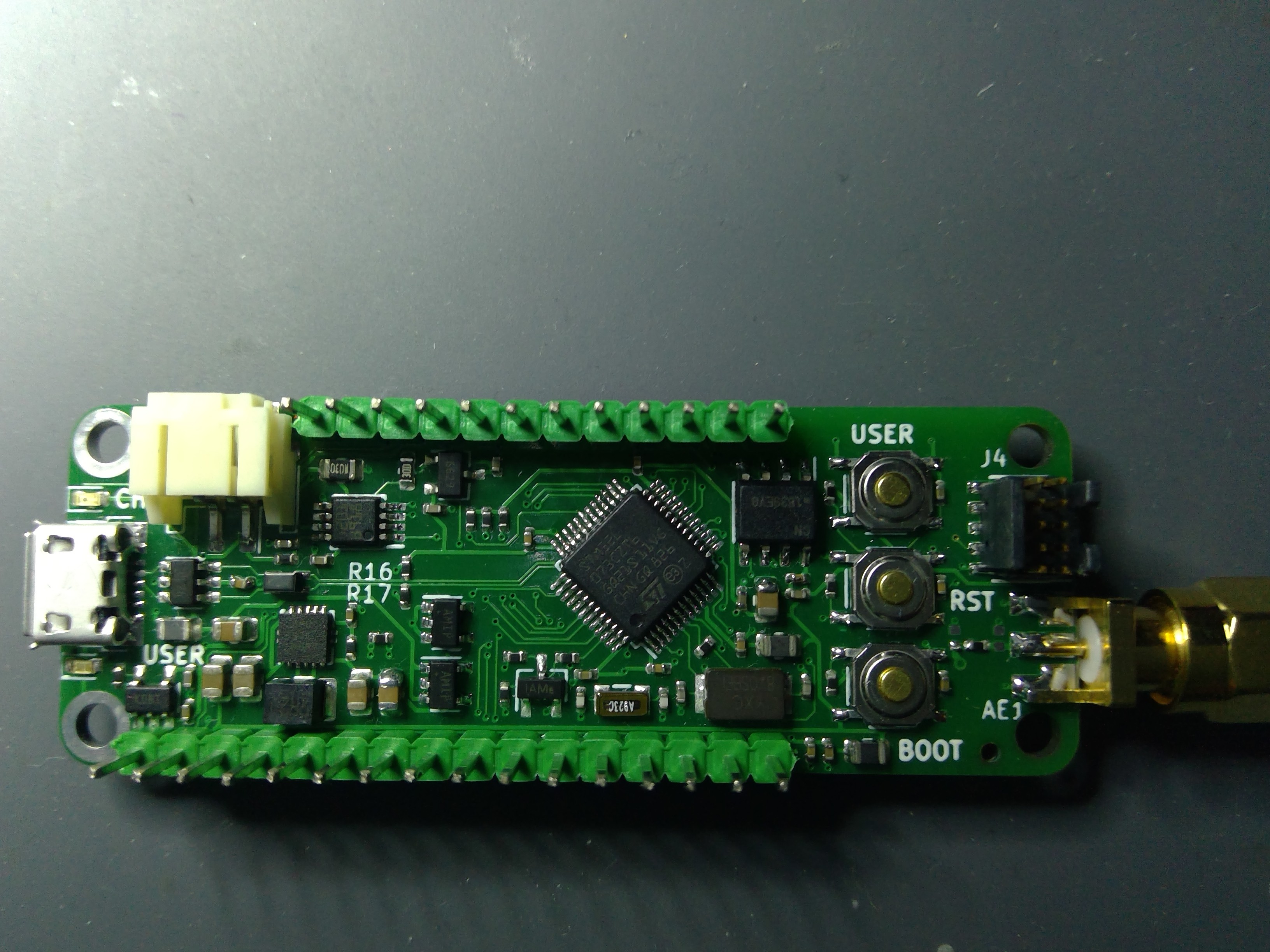
To date, I've done a basic power on test using the 3.3V from a bench supply, the battery and 5V via USB and all function as designed. This tells me that my DC-DC is working, as is the rest of the power system. Battery charging also works.
I loaded up a simple blinky application and it runs, proving my SWD and crystal circuits are working. Only snafu there is that the LED is green instead of red! Probably an error on my end again, but a minor one.
Only issue I've noticed so far is that I populated R16 and R17. With the STM32 USB FS Phy, pullups on the D+/D- line aren't required, but I wanted to have the pads there just in case. I'll have to desolder those when it comes time to test the USB.
My next step is to write some basic code to test the battery fuel gauge and at least make sure I can communicate with the crypto coprocessor.
So far, off to a good start!
 Andy
Andy
Discussions
Become a Hackaday.io Member
Create an account to leave a comment. Already have an account? Log In.