 Paul McClay
(ping "followers": the successor to this project has developed pretty well & continues - since you followed this you may want to follow that)
Thanks Dan Maloney for the very complimentary Hackaday.com post!
Wow. Thanks Elliot Williams and Mike Szczy for your very complimentary conversation leading off Hackaday Podcast 082! (from 2m:40s)
...and the top Highlight tap. You guys have been very kind to this project!
Anyone: if you like this, check out my follow-on project that Elliot mentioned.
Leading with Jolly Wrencher because Hackaday.

Video: milling JW in three operations


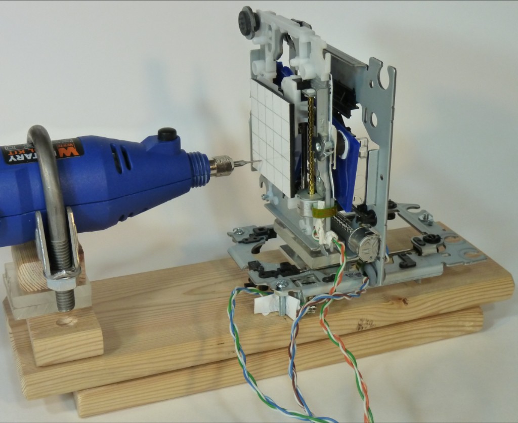
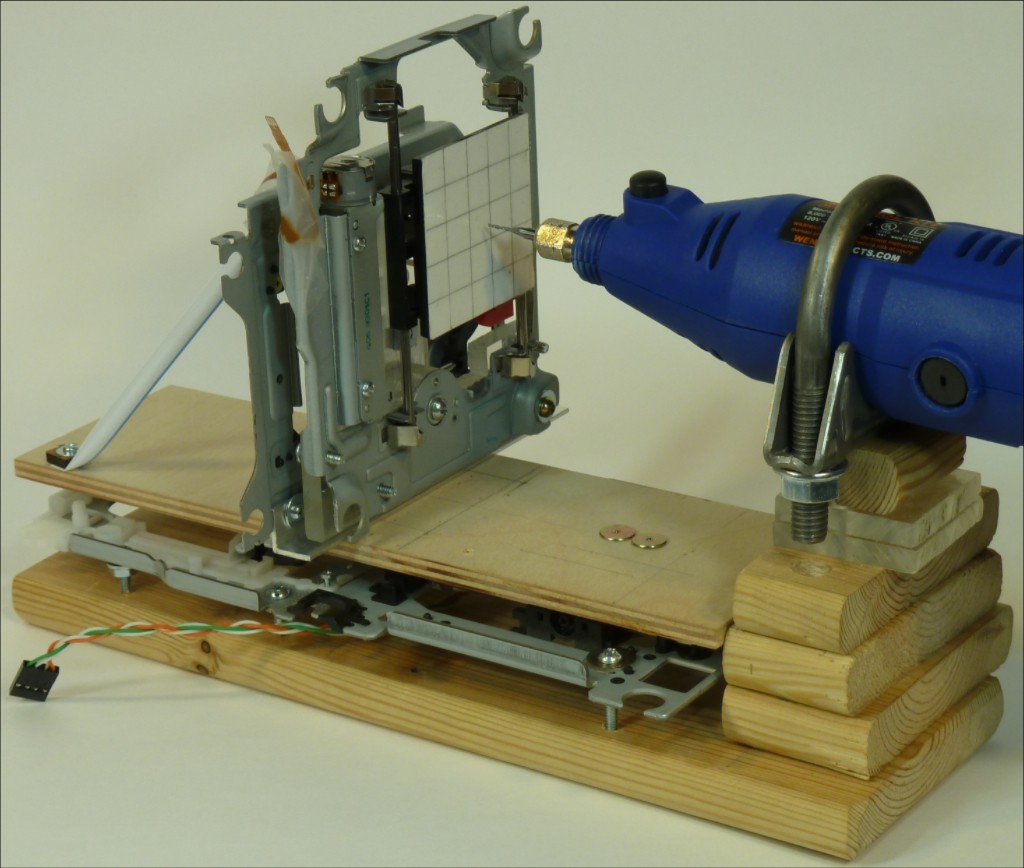
- X - horizontal (perpendicular to spindle)
- Y - vertical
- Z - spindle (horizontal)

Video: 3D interpretation of amazing hackerspace Pumping Station: One's logo.
First?
The guts of discarded CD/DVD drives -- especially those that use a stepper motor and lead screw to drive the optics sled -- provide great building blocks for CNC toys. Many people have shared a little or a lot about their own versions of 2D pen plotters, laser engravers, 3D printers and other clever machines made from CD/DVD drives.
As of writing this, I've found only three efforts to make a three axis mill/router. Of those: two successfully cut light foam and one bravely documented Epic Failure. So at the moment I think the machine described here does something new. If you know of others, please comment!
Coffin Corner
Some high-flying aircraft face a hazard called "coffin corner" where the minimum necessary speed to maintain lift and stay in the air approaches the maximum possible speed to retain wings and stay in the air. When too fast is slightly faster than too slow, flight gets fragile. When too slow is much faster than too fast, none of the things that might happen are stable flight.

Obviously this e-waste lash-up was never going to go fast through hard materials.
While thinking something like this might work even if it could only work slowly, I had maybe heard but didn't really understand there is a limit to how low slow can go in milling.
A milling cutter doesn't work like sandpaper, rubbing away material. Rubbing makes heat and powerful rubbing at one point makes something hot. A spinning ball of melted acrylic may look kinda like it's cutting something, for a while, but it's not and not for long. For a milling cutter to work, the milling machine has to feed the spinning cutter through material rapidly enough that each cutting edge of the spinning tool advances far enough into new material to cut away a distinct chip. In the argot, that's "making chips". So there's the "stall limit" -- can't go too slow.
Trying to step an open-loop stepper motor too fast against too much resistance results in missed steps, and missed steps ruin CNC operations. For stepper driven linear actuators found in CD/DVD drives, the motors are weak and the optics sled engages the lead screw with a sprung follower designed to slip when blocked or back-driven. All aggravated by floppy/springy structure promoting load spikes due to uncontrolled tool engagement. Assuming a build capable of any engagement of tool into material, that chain of weak links becomes the "mach limit" -- can't go too fast.
This project started with too fast nowhere near fast enough to catch too slow and me not understanding the chase. Challenges include getting into "coffin corner" in the first place, and then not breaking out of either limit for the duration of complete CNC operations.
Secret Sauce
This example gets impossible results from inadequate parts because:
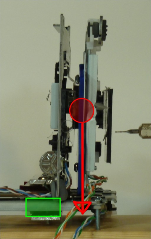
- Heavy parts move horizontally. Only the Y sled and workpiece move vertically.
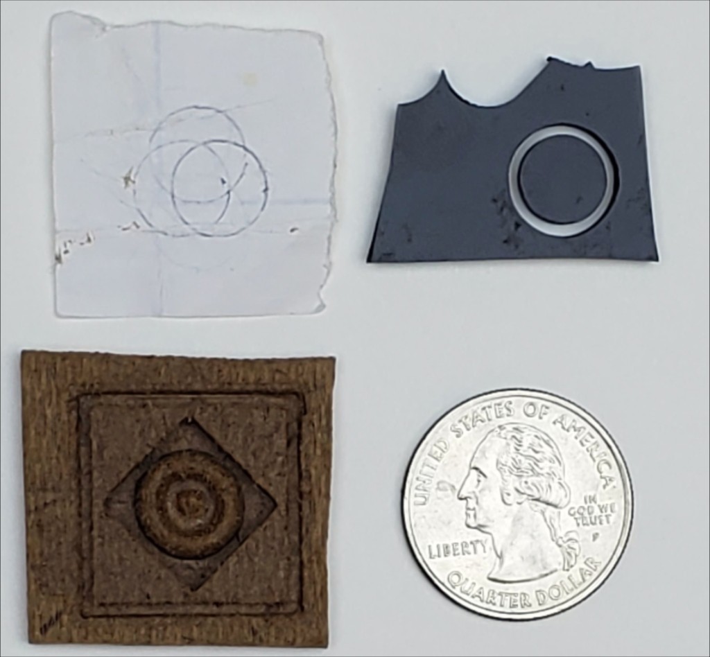
- Shims. Remarkably, IMO, much of slop in CD/DVD optical sled axes can be shimmed out. Note the mostly-round small circles in finished parts. However, Z backlash/hysteresis remains awful so...
- "Waterline" tool paths. Parallel paths of varying depth don't work. Waterline paths work because the Z axis always advances to a given cut depth from the same direction.
- Shallow cuts. 0.15 mm step-down is one full motor step with 18° steps and 3 mm lead screw pitch, which helps with consistent Z positioning of heavy spindle.
- Makes chips. Lowest spindle speed and fast enough feed rate so that each advancing tool edge cuts out a distinct chip of material. Shallow cuts and machine rigidity help.
...among other twists and turns. Tweaking up CD/DVD drive linear actuators could spawn its own writeup.
Cheap and Simple
For this project I'm using found/scrap materials and simple hand tools. The first increment of resource escalation would be to jettison the weak CD drive axes, but then this wouldn't be this project anymore.
Materials include irregular pieces of ~3 mm acrylic and hardboard laser cutter waste, aluminum bar stock, "credit card" plastic, toothpicks, wood scraps, random scavenged screws/nuts/washers, a grungy piece of heavier acrylic found in the woods, etc.
Purchased items include long screws (a length of threaded rod & a hacksaw would have worked) + ~50 hex nuts + not that many washers, a couple of automotive exhaust clamps and the right-angle brackets that hold the XY table in the latest build.
The most "special" tools I recall using so far were a set of small screwdrivers, a 6-32 tap and a pin vise with a few small drill bits.
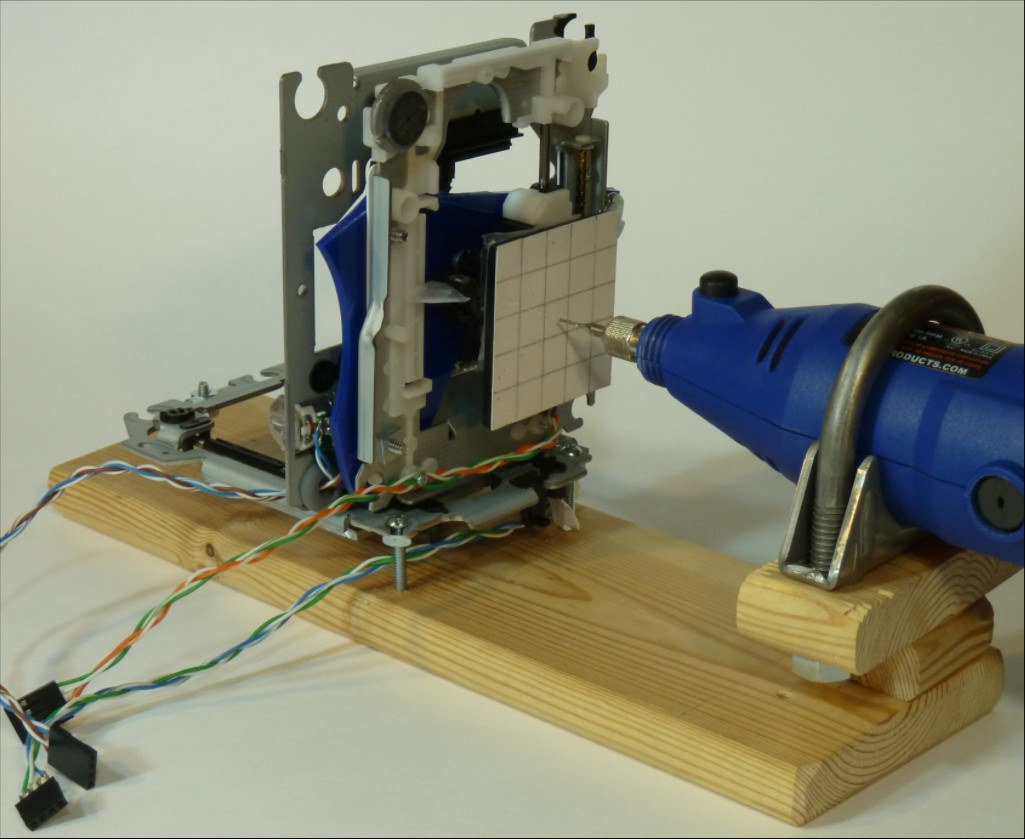
For a low-fabrication fixture for the Dremel-clone rotary tool I found a nearly perfect solution in saddle type exhaust clamps with a nominal size (tube i.d.) 1/8 inch under the required diameter (tube o.d.). In earlier iterations a single clamp held the tool securely. The current build uses two clamp saddles.
Buying the right-angle brackets was just an impatient cheat.
A Few Build Notes
Construction so far has entailed much iterative improvisation around awkwardly shaped components with available materials. Anyone else will have a different collection of donor drives and "stuff" at hand, so there is no "how to" here. But here are a few notes.
No hot glue, epoxy, e6000 etc.! No permanent assemblies. Essentially all of this machine has been built up, broken down, revised, rebuilt or replaced several times over. Parts are selected/cut/carved/drilled/fettled to fit and mostly screwed together with a variety of scavenged small screws. $cotch brand "Permanent Double-$ided Tape" works in some places for an adequate but not inseperable bond. Beware some generic alternatives use crap adhesive on one side that's ok in tension but practically grease in shear.
Flipping the X axis (horizontal axis of the two-axis assembly) might simplify a similar build. Stiffly attaching the Y frame to the X sled without adding bulk between them kept me busy for a while. Twice. At least. I attached the X frame to the base (Z sled in earlier versions) and Y frame to the X sled to avoid cantilever load on the X sled. The current layout maybe doesn't require that bit of optimization. Fixing the X sled to the base and pinning the X & Y frames together would simplify construction.
Lots of similar projects fix the sled frame corners between two nuts on a screw for simple adjustability. Re-adjusting after removing and re-installing axes got old so I added a couple more nuts at each corner to a) jam the screw in the base so the screw doesn't turn, and b) jam the tediously adjusted lower nut that sets the position of that frame corner. Now it's no big deal to de-mount & re-mount X & Z frames that attach to the base.
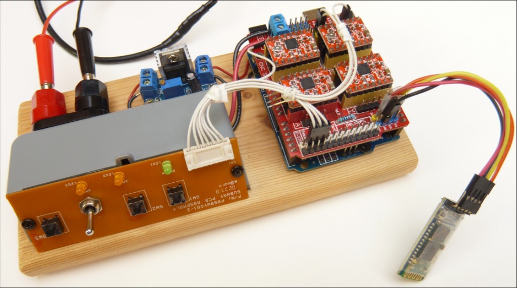
Grbl
I built up the Grbl and motor driver electronics as a separate unit rather than assuming any stable machine to attach parts to. More about that here.
CAD
I like Onshape.
CAM
Fusion 360 CAM seems to be the current top dog for hobbyists. Windows gives me hives & I lack a Mac so I looked for alternatives...
- Kiri:Moto is available within OnShape. I used Kiri:Moto for essentially all of thrashing with this from zero to a machine that worked well enough to cut my test part. To actually use the thing to make something else, I wanted to generate a "rest" operation and afaik Kiri:Moto doesn't do that. Now I see that the author has resumed active development so I'll be giving that another look.
- N̶o̶t̶e̶ ̶K̶i̶r̶i̶:̶M̶o̶t̶o̶ ̶h̶a̶s̶ ̶s̶o̶m̶e̶ ̶p̶r̶e̶c̶i̶s̶i̶o̶n̶ ̶l̶i̶m̶i̶t̶ ̶t̶h̶a̶t̶ ̶m̶a̶k̶e̶s̶ ̶s̶u̶b̶-̶m̶m̶ ̶s̶t̶e̶p̶-̶d̶o̶w̶n̶s̶ ̶u̶n̶e̶v̶e̶n̶.̶ ̶I̶t̶'̶s̶ ̶n̶o̶t̶ ̶t̶h̶e̶ ̶'̶t̶o̶l̶l̶e̶r̶a̶n̶c̶e̶'̶ ̶p̶a̶r̶a̶m̶e̶t̶e̶r̶.̶ ̶T̶o̶ ̶g̶e̶t̶ ̶a̶r̶o̶u̶n̶d̶ ̶t̶h̶a̶t̶ ̶I̶ ̶s̶c̶a̶l̶e̶d̶ ̶t̶h̶e̶ ̶m̶o̶d̶e̶l̶,̶ ̶K̶i̶r̶i̶ ̶&̶ ̶G̶r̶b̶l̶ ̶p̶a̶r̶a̶m̶e̶t̶e̶r̶s̶ ̶b̶y̶ ̶1̶0̶x̶/̶0̶.̶1̶x̶ This appears to be solved.
- MecSoft's VisualCAMc is also available within Onshape. Conveniently MecSoft ran an open beta of the Onshape integration while I was looking. That was great. But now it's $99/mo.
- MecSoft offers FreeMILL also. That sounds like the right kind of thing but no joy. This machine has too much Z hysteresis to do parallel 3D paths and FreeMILL only does parallel paths.
- FreeCAD has a CAM workbench. The 3D pocket operation was in early development when I first looked and I wasn't getting happy results. Development has continued so presumably it's getting better. I looked again when I wanted to CAM the PS:1 snowflake and IIRC it got confused by the pocket with sub pockets. It probably handles simpler stuff ok. There's also the lack of rest operations. Development continues so I expect to look at that again.
...and ended up back at Fusion 360 to generate tool paths for the objects shown above.
Past
First
I started with the idea of building as compactly as possible to minimize offsets between axis rails and whatever was supposed to move on them.
- fixed spindle
- X - horizontal (perpendicular to spindle)
- Y - vertical (perpendicular to spindle)
- Z - toward/away from spindle
(Note the entirely random blue acrylic piece spanning the Y frame to provide an attachment to the X sled. Other randomness of material is plentiful if less visible.)
Bringing the XY axes down close to the Z axis meant shifting them off the top of the Z sled creating an overhanging load, which is not a good thing. So there's a trade-off. A MechE might have known, or analyzed, which way the trade should go. I guessed.
Although the Z axis wasn't reliable, this build was able to move throughout the full extent of all axes, draw fairly round circles (low XY backlash) and scratch a circle in some acrylic with an unsuitable rotary tool bit. After I ordered some 1 mm end mills, it cut a clean circle out of ~3mm acrylic and cut most of a test piece in hardboard. None of that on the first try. For the test piece it completed the pocket but died cutting the profile around it. We'll see the test piece again -- I have a bag of malformed examples.
Second
To cure the balky Z axis, I reversed the offset/overhang trade and put the XY axes on top of the Z sled. This version produced the first good copies of my test part, and was getting close to "working"...

But then I burned the X axis motor. I claim the aforesaid crap tape made me do it. Since I haven't had two of the same CD/DVD/BD drive to scavenge, every optics actuator is different and replacing means remaking whatever it attached to.
Third
A nearly complete rebuild followed scrounging some more optical drives. One of the "new" mechanisms from a BD player had a dual-lens sled with the lenses separated radially and consequently longer sled travel. Including that made the work area noticeably larger. With the dead motor removed, the old X axis became a simple slider. I tried using that to stabilize the Z axis with moderate compromise to the idea of doing this with three sleds. Getting two sleds between warped boards to move freely took a couple of tries.
The extended Z axis platform made a place to stick a cut-up juice bottle to serve as a vacuum dust collector. The overwhelming noise in the video below is the vacuum cleaner. It worked, but between the noise and the tedium of suspending the vacuum hose ~perfectly to apply ~zero force to the moving bottle, the vacuum part of that idea didn't get a second try.
This major rebuild turned out to be no great improvement over build #2. I think because the 1/16 inch aluminum angle holding the XY axes flexed too much. Before troubleshooting that any more than a lazy try at bracing, I figured out that the tandem sled arrangement cured my reason for stacking all three axes together vs. moving the spindle in Z. So this whole rebuild went down the drain of failure to review earlier decisions in light of adjusted parameters.
Fourth
The next try became the "capable" machine milling the fairly complex PS:1 & JW pieces shown at the top of this page. After mangling a few test pieces to get it dialed in, it turned out both of those pieces on the first try without trouble. Woot.
Future
- I wrote above that the first step of resource escalation would be to jettison the weak CD/DVD drive parts. While thrashing on this I was also thinking about what a minimal meaningful next step up could be and I think I have an idea. I've made some test parts to validate the basic idea and it seems to work.
- Those (vid) and a proto XY table look very encouraging. And that's a project now. Next thing (in this context) is to get through a complete build of that idea. That would jump from ~100% hand work to ~100% laser cut. And that would make it reproducible. And Instructables has a CNC contest going.
- Back to this machine: try replacing the Dremel-clone with an HDD motor for an all-eWaste machine. I've made up an {HDD motor+collet holder} that seems capable, but don't know how well the driver chip will stand up to presumably greater current working against ~continous increased drag. Extra cooling? Replace HDD controller with an ESC? (but then less eWasty)
- Practical/useful Z probing on the hypothetical new machine? current machine?
- Limit switches & homing on the hypothetical new machine? current machine?
- Replacing the X axis of the current machine? A tighter sled in hand now and different (better understood) configuration might significantly improve the machine. But for what purpose?
- Check out current state of Kiri:Moto and FreeCAD
- Check Fusion-generated tool paths I've cut so far to see if they accomplish anything indispensable that Kiri or FreeCAD couldn't do adequately enough.
- Write more about tweaking up CD/DVD drive sleds?
- Clean up & share 3Dish Jolly Wrencher model? Does HaD care? Does HaD want it?