 Ken Yap
As mentioned, the schematic is taken straight out of datasheets so I didn't expect any problems, nor did I encounter any. It was insanely easy to get working.
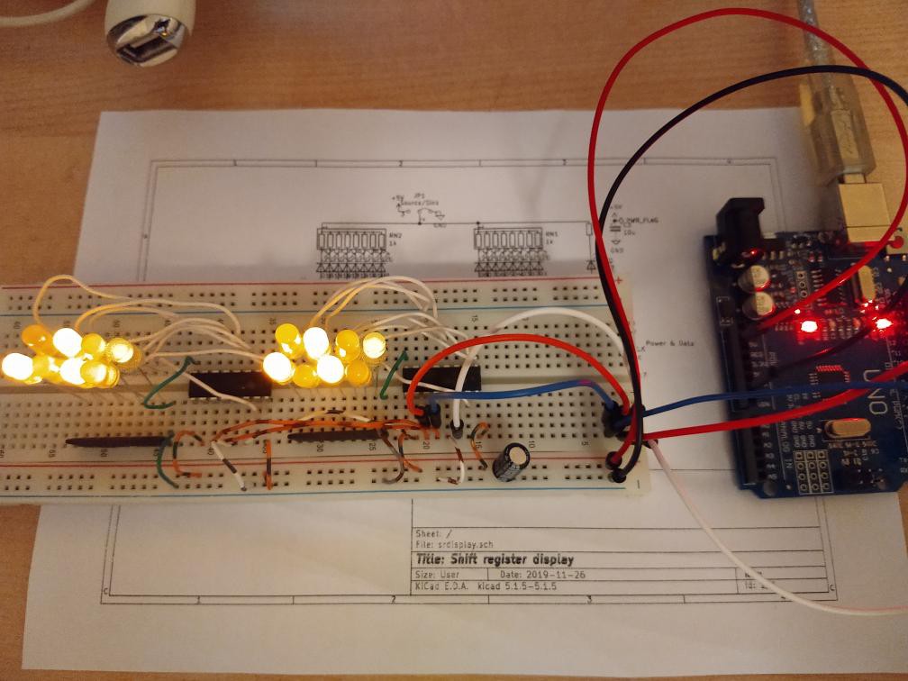
After putting the components on a breadboard, and doing an anti-smoke accident check, I connected it up to an Arduino Uno to test it.
Except for one LED plugged in backwards, which I corrected, the test program worked first time. Here it is:
/*
   Test shift register display
*/

#define DATA    2
#define CLOCK   3
#define LOAD    4

void setup() {
  // put your setup code here, to run once:
  pinMode(DATA, OUTPUT);
  pinMode(CLOCK, OUTPUT);
  pinMode(LOAD, OUTPUT);
  digitalWrite(DATA, LOW);
  digitalWrite(CLOCK, LOW);
  digitalWrite(LOAD, LOW);
}

void writebyte(unsigned int i) {
  for (byte mask = 0x80; mask != 0; mask >>= 1) {
    digitalWrite(DATA, i & mask ? HIGH : LOW);
    delayMicroseconds(10);
    digitalWrite(CLOCK, HIGH);
    delayMicroseconds(10);
    digitalWrite(CLOCK, LOW);
    delayMicroseconds(10);
  }
}

void load() {
  digitalWrite(LOAD, HIGH);
  delayMicroseconds(10);
  digitalWrite(LOAD, LOW);
  delayMicroseconds(10);
}

void write2bytes(unsigned int i, unsigned int j) {
  writebyte(i);    // MSB
  writebyte(j);    // LSB
  load();
}

void loop() {
  // put your main code here, to run repeatedly:
  for (unsigned int i = 0; i < 256; i++) {
    write2bytes(i, i);
    delay(250);
  }
}
All that the program does is repeatedly display an 8-bit counter as binary on the two columns of LEDs in parallel, at the rate of 4 per second. This rather than display one 16-bit counter as I don't want to wait 5 hours to see the whole cycle.
The CLOCK and LOAD lines are pulsed for 10 microseconds. This implies a maximum data rate of 50,000 bits/second, far more than adequate for this kind of display. I limit the rate so that the wiring isn't critical as it might be at a higher rate.
Next step will be to get the board fabricated.
Discussions
Become a Hackaday.io Member
Create an account to leave a comment. Already have an account? Log In.