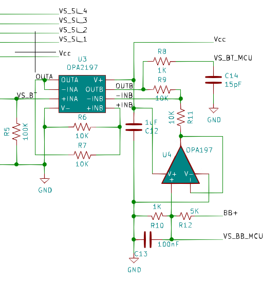
During early testing I discovered an oversight with the differential amp design. Its balance bus reference, which also serves as the sense input to the controller, did not have a buffer. This resulted in 30mV+ offsets in balance bus measurements, so I hacked in a buffer using another OPA197. U4 provides a low impedance drive for the differential amp and keeps the sense signal noise free.
As mentioned in the previous post this Balancer may at best be described as an awkward design because it requires a good deal of setup for the specific stack and management from the controller during operation. I believe that most balancers for the type of battery stacks this design is intended for achieve balancing thru transformer action: each battery has some form of transformer based converter (e.g. forward) with a winding ratio equal to that of the stack. That is, the primary is connected to the full stack, say 4x12=48V, and the secondary to the battery. This design can run continuously, and the current delivered to each battery can be monitored, instead of voltage, to establish health.
So, here's my run-down of problems with this design.
- Battery safety management is especially important with this design due to the use of unregulated flybacks. The prior log, Balancer Complete, described the protection circuits. The Battery Management Systems (BMS) in LFPs, particularly cheaper ones, tend to open inconsistently at both the fully charged & discharged ends. The balancer must respond quickly to prevent damage.
- The balance bus battery is a necessary complication in this design. It provides the bulk charge to augment transfers between batteries because the intrinsic transfer efficiency is poor (~77%). Hence, it is constantly in a state of discharge which requires transfers from batteries in the stack, which in turn unbalances the batteries. So the balancer plays a perpetual game of musical charge which, depending on the capacity (Ah) of the stack, reduces run-time. This could be addressed by making charge transfers asymmetrical (pull more charge out of high battery, push less into low). Ideally the balance bus battery is eliminated by powering the bias supplies from the stack; but the balancer would not work since the balancer side of the flybacks are powered from it.
- While this design demonstrates the ability to combine battery voltage measurements with a simple charge transfer mechanism, better data acquisition hardware is required. The balancer has demonstrated that it can measure reliably to about 50mV of resolution, but this is a relative measurement to other batteries in the stack and not absolute voltage. The main problem lies with the resolution and speed of the ADC and lack of any summing / integration capability.
- Even with better data acquisition, the intrinsic design has two additional challenges:
- Battery voltage settling time. Determining charge state by voltage alone is notoriously difficult. Accurate State Of Charge (SOC) requires that the battery be idle for up to 30 minutes: impractical. The balancer is polling batteries every minute. A battery that received charge a minute ago will reflect a higher voltage than its true SOC.
- Measuring batteries with a time varying load, such as an inverter, will give false results. This effect is magnified if the battery stack is small (lower Ah capacity) relative to the load. This happens because batteries are measure sequentially. In the current design the delay between measurements is 2~4mS: 4mS is approximately one quarter of a 60Hz sine wave. Faster acquisition hardware can eliminate most, but not all of this. Alternatively, multiple ADCs could be employed at the expense of considerably higher cost & complexity.
- The requirement to use timed transfers makes the configuration for a particular stack & balance bus battery combo time consuming. It must be done largely by trial & error; even rule of thumb math isn't of much help because the relationship between battery voltage & SOC is non-linear. I guess you could say that one small advantage of this design is that it can scale to stacks of different voltages without changing the individual balancer sections.
Experience
The litmus test for anything is "Would you recommend it?" Sadly, I'd have to answer with a resounding no. That's not to say I'm sorry I built it: I have gained invaluable experience and I've added some useful stuff to my tool belt. And, in spite of its shortcomings, it has proven to be remarkably hardy. I've done some pretty stupid things with it, and aside from a blown fuse or two it hasn't skipped a beat.
Discussions
Become a Hackaday.io Member
Create an account to leave a comment. Already have an account? Log In.