 Michael Gardi
The ALU presented in the book was even more massive than the Binary to Decimal Decoder consisting of 39 DPDT and 5 SPDT blade switches mounted of a 24 x 36 inch board. Like the Decoder the ALU switches were physically "ganged" together to perform the ADDition and SUBtraction operations.
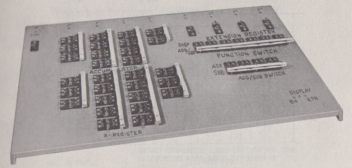
The panel was laid out like this:
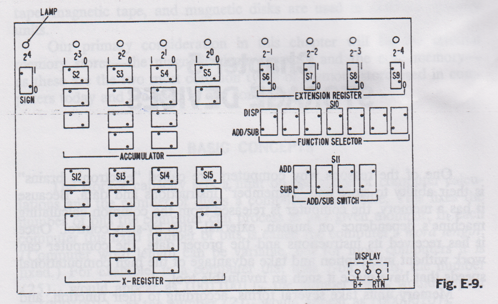
In addition to the "sets" of switches to enter the Sign, Accumulator, X-Register, and Extension Register binary values, there were switches to choose between Functions (Display or Add/Sub) and the Operations themselves (Add or Sub). Now with the new ALU functionality baked into the Relay Based ALU PCB, this layout can be simplified quite a bit. Here is my ALU Panel:
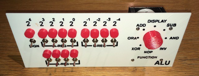
I've incorporated DISPLAY into my single FUNCTION selector switch and added 5 new operations: ORA, AND, XOR, INV, and NOP. As with the Binary to Decimal Decoder the PCB will be mounted behind the panel. Time to get wiring.
Discussions
Become a Hackaday.io Member
Create an account to leave a comment. Already have an account? Log In.