Hello to everyone!
On my research journey, I already talked about the WHUZY Audio ZK-1002 amplifier board but it is worth it to dive more deeply into that board and I bought it again lately.
1. THE NEW NAME
The new news is that probably you can't buy the "WHUZY" anymore: searching and buying "ZK-1002" I received the ZZ-1002 by ZIZHI Audio instead. Well, it's really the same board tho.
2. NEW NAME, OLD PROBLEM
Let me remind you about the problem with the AUX input stage of those boards: there is an RC filter with the wrong "C" value (10nF instead of 1nF) so the low-pass filter starts at 3.5kHz instead of 35kHz. I'm talking about C41 and C42, with R2 and R4 (4.65kOhm). To get back your hi frequency you must swap in the correct 1nF capacitors or you can remove them also; the remaining resistors will lower a small bit the volume (negligible), you could remove R2 and R4 too, and then bridge the pads.
There is also a cut-out with a curve starting from 150hz down to 20hz due to the low value of the decoupling capacitors C37 and C39 (100nF): to fix this you must replace them with a 1uF instead (value from 0.47uF are good).
Another problem is that the Bluetooth chip is always on (and the TPA3116 are on standby), but this turns out only annoying and not acoustically problematic.
3. THE HIDDEN PROBLEM (yes, another one!)
You have this board and when you rotate the volume POT you hear a scratching noise, but you are like "ah ok this POT is a cheap one but it's ok". Right?? you are WRONG, it's not "ok" and the scratching noise doesn't come from a cheap POT... the truth is much more insidious!
The second stage before the POT is the Bluetooth one, with the IC by JieLi. This IC elevates the input audio signal (from AUX) and the output signal to the amplifier with 1.8v of DC current. Yes, DC current into the POT, that's the scratching sound you're hearing! Also, the fact you're hearing that, means that a DC current is going into your speakers! (tested it with a voltmeter and oscilloscope)
Basically, the circuit design is wrong.
4. HACK A FIX
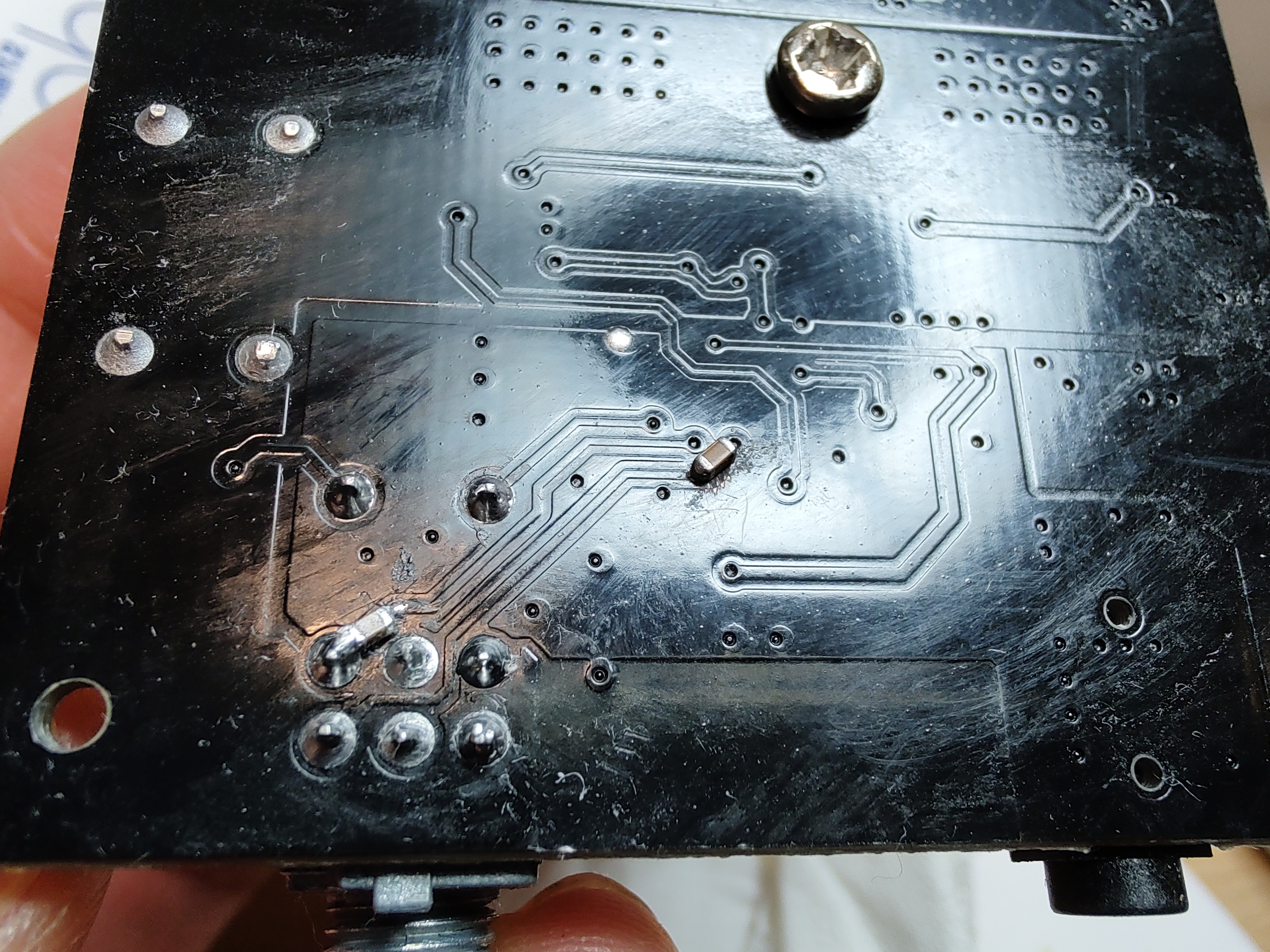
Well, electronically speaking it's just a matter of adding 2 more decoupling capacitors on the output of the Bluetooth chip, but to do so you have to cut 2 PCB traces. Here is my fix:

As you can see I worked on the bottom of the PCB: is the only place before the POT with enough space.
You must cut the traces, remove a bit of protective paint, and then solder on an SMD capacitor, I did it but I won't lie to you: it's a very hardcore fix, not for newbies.
Did it work? Oh yes, it works now, smooth and silent! But unfortunately is not for everyone.
5. FINAL THOUGHTS
And here we are again, I paid 14.70€ shipped for this board, but at the end of the day I can suggest to ANYONE to buy it, and it's really a shame; I'm so frustrated by this that I'm thinking to design one by myself... Should I? ;)
Thanks for reading me and stay safe.
Davide, baugrafik
 Davide Ercolano
Discussions
Become a Hackaday.io Member
Create an account to leave a comment. Already have an account? Log In.
Could you tell me the value of the two capacitors at the bottom to solve the alternating current problem?
Are you sure? yes | no
Really sorry for a long time to reply!
It's a decoupling capacitor on the audio path, so anything from 0.47 to 2.2 is good. I used 1uF.
PS.: it's not "alternating current" but "DC current" tho.
Are you sure? yes | no
Great!, Thanks for your response.
Are you sure? yes | no
Hello. Excuse my English.
I want to buy 2 amplifiers to connect 4 BodyShakers in parallel, configuration: 1amp x 2 bodyshakers (Left and Right) X2.
I'm not going to use the Aux input, I don't need it, so I wouldn't have to modify anything?
You understand a lot about this, I don't, so can you help me? Do you recommend this board for this purpose?
They also sell this:
https://es.aliexpress.com/item/1005004933647349.html?spm=a2g0o.cart.0.0.10217a9d3Qkf6h&mp=1&gatewayAdapt=glo2eng
It's cheaper and it doesn't have bluetooth or AUX, but I don't care because I'm not going to use it, but I think the materials (Capacitors and inductors) are of worse quality, right?
Thank You.
Are you sure? yes | no
Hello, very sorry for a long time to reply!
If you don't need the first stage (pre-amplifier stage) then the board you linked is pretty good.
About the capacitors and inductors, they are also of good quality, but there would be a need to verify the LC filter checking if the inductors get hot and if the frequency response is complete
Are you sure? yes | no