The finished project will have six 4x4 arrays of LEDs. Each array will consist of four 2x2 PCBs, arranged in a square. We have to make our own PCBs for this because we need each LED to be pretty bright. We couldn't find anything off-the-shelf that (1) has bright enough LEDs, (2) is cheap enough, and (3) will be easy to mount in a grid.
These PCBs use primarily surface-mount components, so that we can do reflow assembly. They'll probably take about an hour to assemble and test. The process is standard for DIY surface mount assembly - use a stencil to apply solder paste, hand place the components, and reflow the solder in a toaster oven.
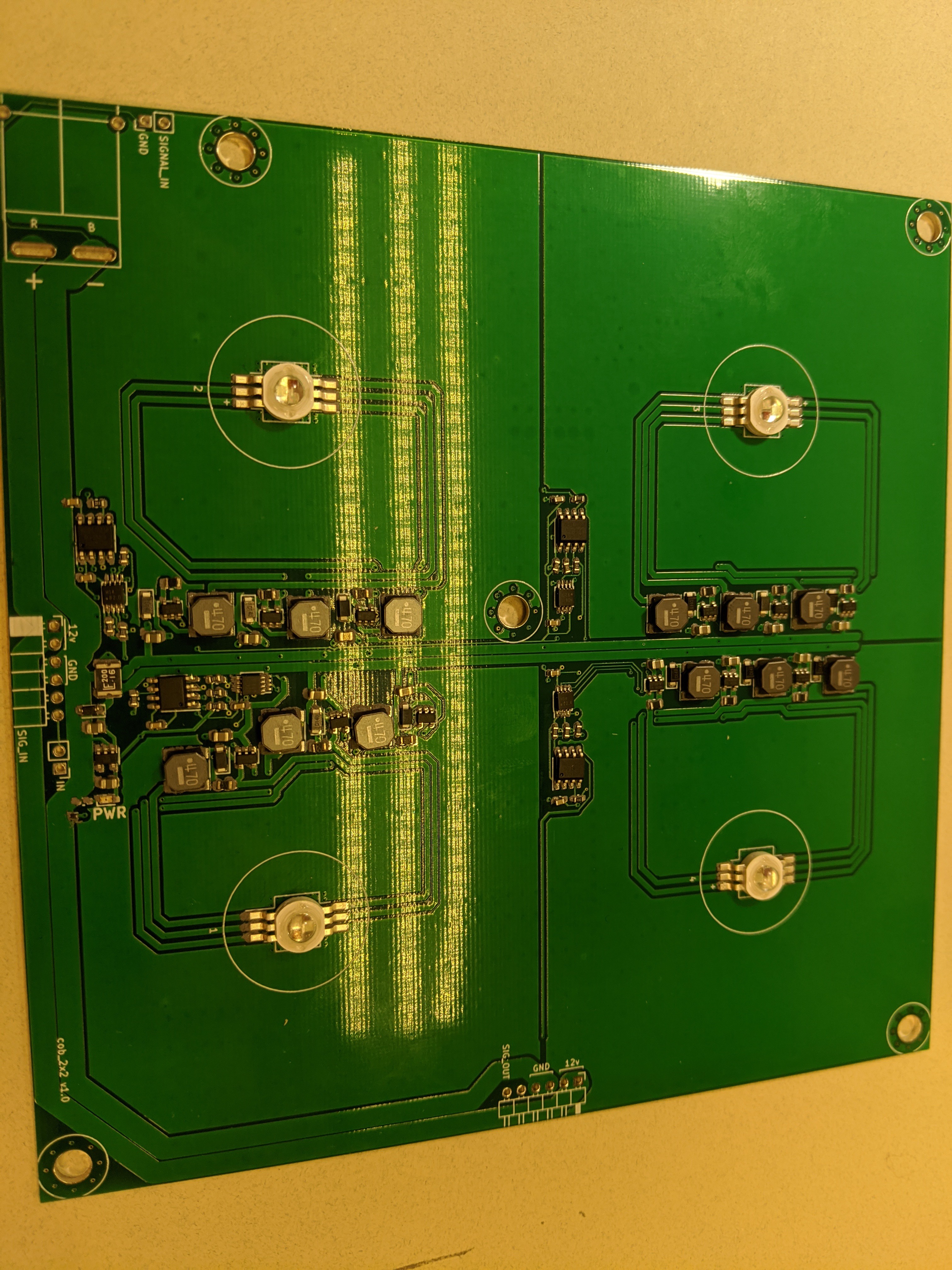
Here's one of the PCBs. The parts have been placed, but not reflowed yet.

There are connectors on two sides so that the boards will tile.
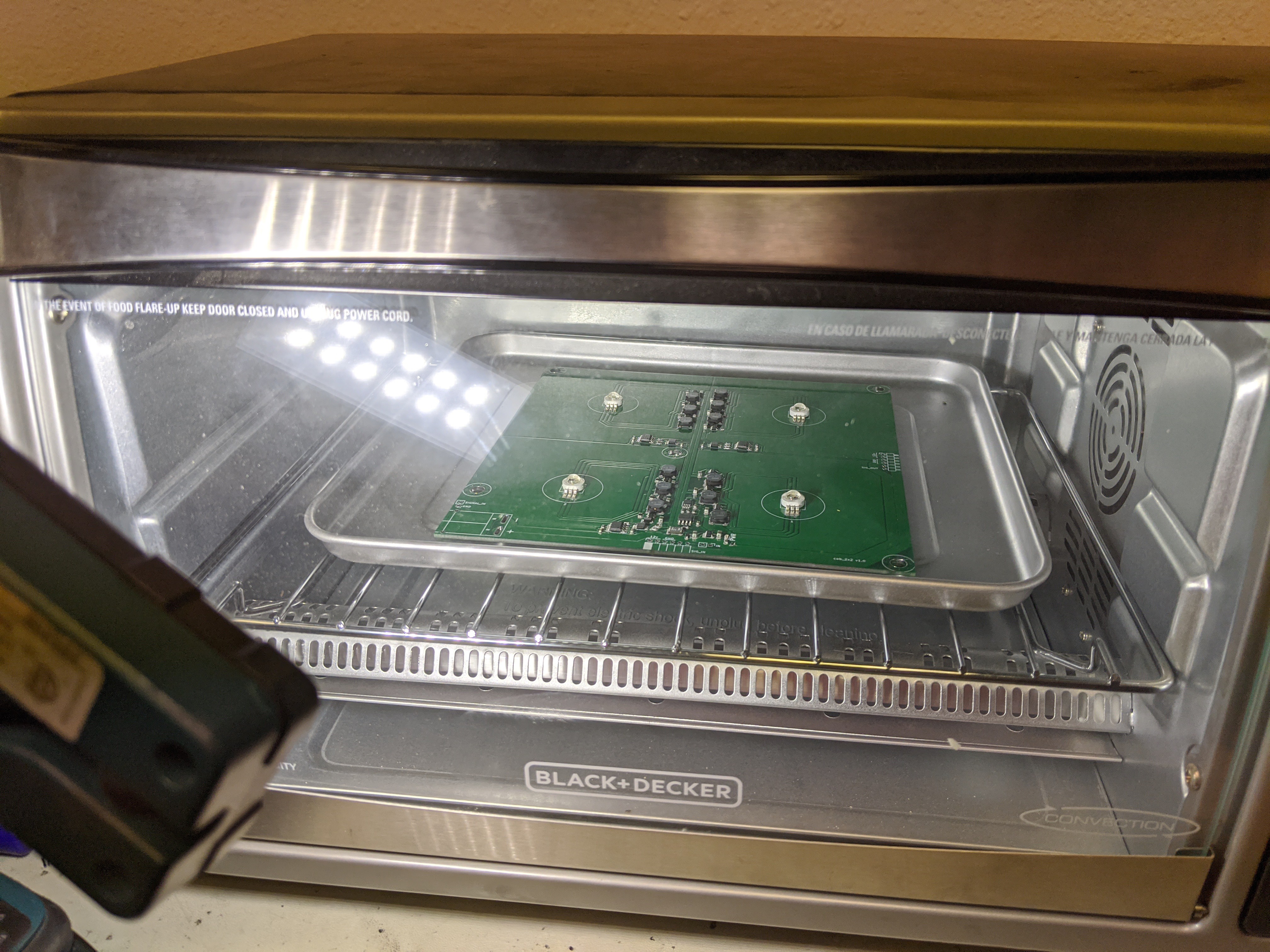
Here's that board in our toaster oven (with convection!):

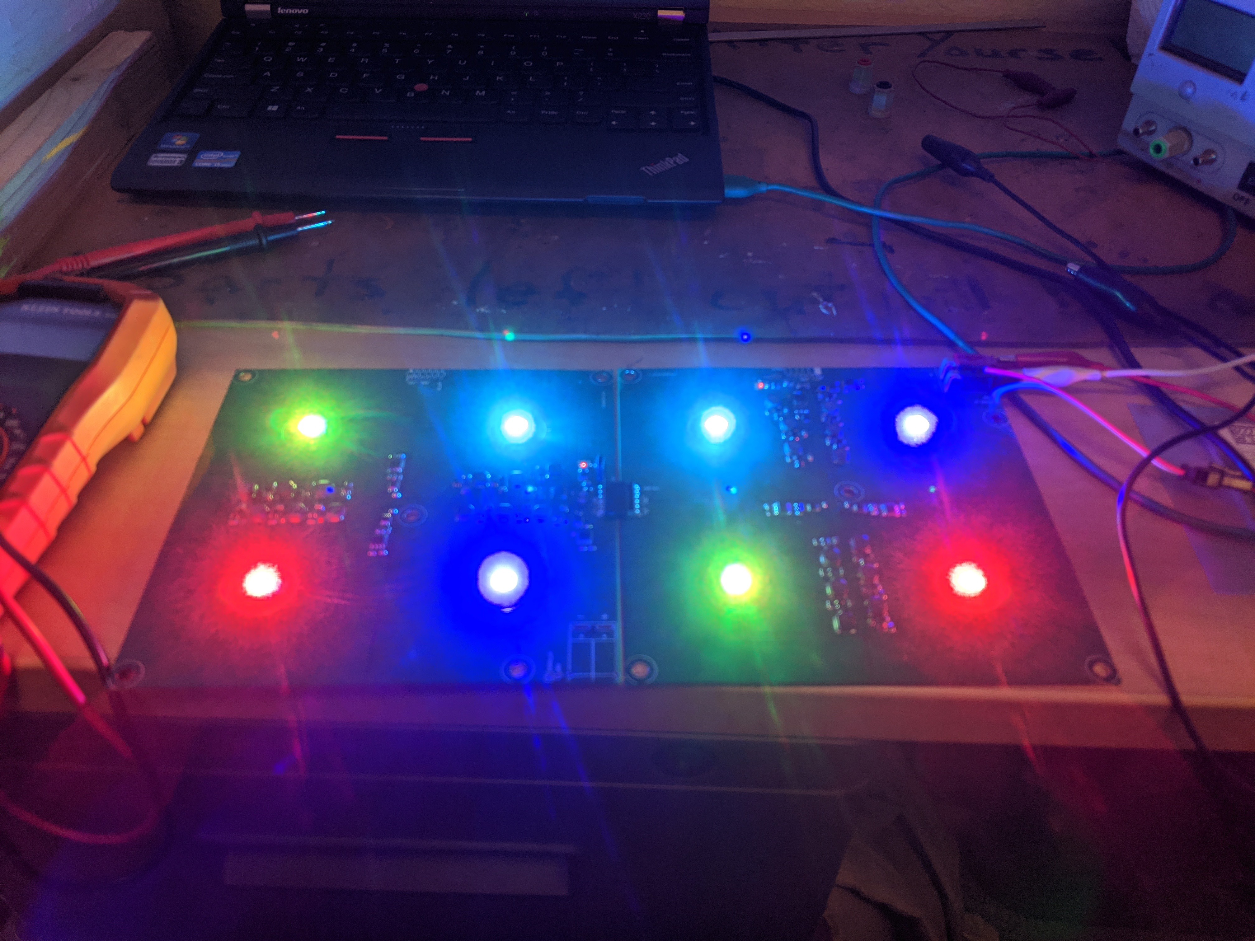
We tested that the boards tile successfully:

Design
The LED boards use the WS2811 chip to control the LEDs. This means that they can be controlled using standard software (e.g. FastLED). The WS2811s control constant-current LED drivers. These drivers are essentially a switching-mode power supply with current sense.
The boards are designed to run directly off of 12v. The control electronics are 5v, so there is a small onboard linear regulator.
We're concerned about robustness, since these will be installed in a harsh environment. We included a couple of features to make the design less likely to fail. The 12V power input has a PTC (resettable) fuse and a TVS diode. This should protect against transients (e.g. static shocks), and against hooking up the board backwards. There is also a TVS diode on the data input, again to protect against transients such as static shocks.
Thermal Considerations
These LEDs are quite bright. They are "9W" LEDs. The actual ratings are 700mA per color, 3.0-3.6v for green and blue, and 2.0-2.6v for red. With that much power, the LEDs need significant heatsinking. The PCB has a large copper area around the LED to dissipate heat. According to this helpful article, the thermal resistance of this heatsink should be around 25C/W. We expect to run the LEDs at no more than half brightness, so the worst-case total power consumption is ~3.2W. An LED turns about 70% of incoming power to heat, so we need to dissipate about 2.2W of heat. At 25C/W, this means the LED will be 55C above ambient. We plan to run this outdoors at night, where the air temperatures should be <20C. This means we should have a peak LED temperature of 75C. In reality, the LEDs will probably have a much lower duty cycle, so hopefully they will stay cooler.
 Adam Demuri
Discussions
Become a Hackaday.io Member
Create an account to leave a comment. Already have an account? Log In.
Hey Adam,
I've been totally digging your work, especially this 2x2 LED boards is really nice. I'm in the process of designing a stage with a lot of small spotlights with ws2811 and 3W RGB LED, and your project caught my eye. It would be awesome if you could share your design files, like the schematics and PCB layout. They could be a great help for me and others who are into creating similar art projects.
Thanks for considering it, man. Eagerly waiting for your response and excited to follow more of your innovative projects in the future.
Cheers,
Patrick
Are you sure? yes | no