 Florian
Now, let's look for information regarding the RAC adapter. Thanks to the pdf file I found the other day, I at least know its product number: PSC-6RAD.
I initially searched for a high-resolution image so I could try to identify the connector that plugs into the air conditioner mainboard, along with its pinout.
But even after a few hours on Google, all I could find is this (credit to https://shop.charles-hasler.ch):
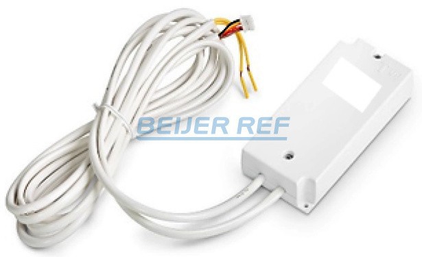
It looks like a 4-pin connector, and from left to right: black, yellow, red, brown?
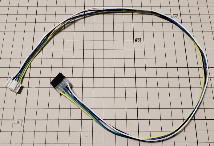
I tried again to find a better image by searching through listings on Ebay and others sites, and I managed to find this auction listing on a site that archives past ads from Yahoo Auction. The selling price of 1000 yens for 3 units really surprised me, but most importantly, there was the following close-up photo of the connector.
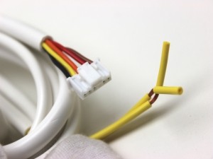
I'm glad I found a better image because it turns out it's actually a 6-pin connector (with only 5 pins being used): black - yellow - orange - red and brown. This reminds me of this Hackaday project, and since my air conditioner is also designed by a Japanese company, I'm hoping this connector has a similar pinout (12V - GND - 5V - TX - RX).
However, after looking at this photo numerous time, I realized that I might have the exact same connector on a dust detector I salvaged from my old air purifier and humidifier combo. If so, I could plug that in the air conditioner mainboard and poke at it with a multimeter to figure out the pinout.
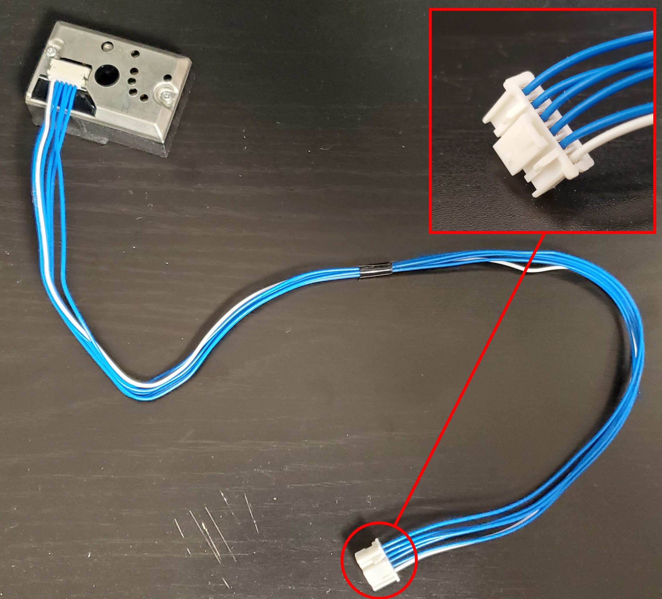
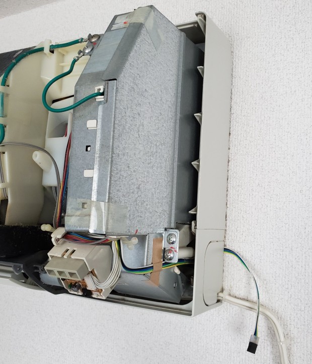
Yes, it's the same connector! Let's just cut that cable, open the air conditioner, locate the CN7 connector, plug it in, and use a multimeter to poke around. I removed the top cover of the air conditioner following the manual's instructions, and after removing a metal cover enclosing the mainboard, here we are.
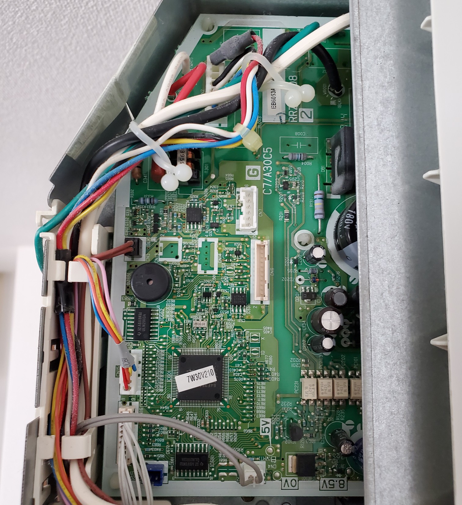
At first glance, I easily identified the CN7 connector, but also noticed these four test points: 5V, 0V, 8.5V and 12V (the 12V test point was hidden to the right of the 8.5V one). So, I connected my cable and, without powering anything on, I checked for continuity between each pin and each test point. The result turned out a little bit different than what I expected: from top to bottom, I got X - GND - X - X - X - 12V. This means that, based on the connector photo I found, yellow is GND and brown is 12V... "Things are not always what they seem". Under power, I indeed had 12V on that last pin and all remaining pins showed 5V, except that 4th pin which seems to be unused.
Since I had already opened the air conditioner and had a proper connector, and the all-blue wire cable was really difficult to work with I made my own cable and plugged it in. This way, I'll be able to easily poking around in the future.
This time, I managed to identify the connector that plugs into CN7 and a part of its pinout. I also now have a cable hanging out of my air conditioner, allowing me to easily probe it. All that's left to do is keep looking for more information and figure out or find the rest of the pinout.
Discussions
Become a Hackaday.io Member
Create an account to leave a comment. Already have an account? Log In.