In this second log I will introduce the electronics used in this project and design the frame to hold the light guides that I designed in the previous log. At the end of this article you will see a first teaser of the fully functional light system for the clock. Let's dive into it!
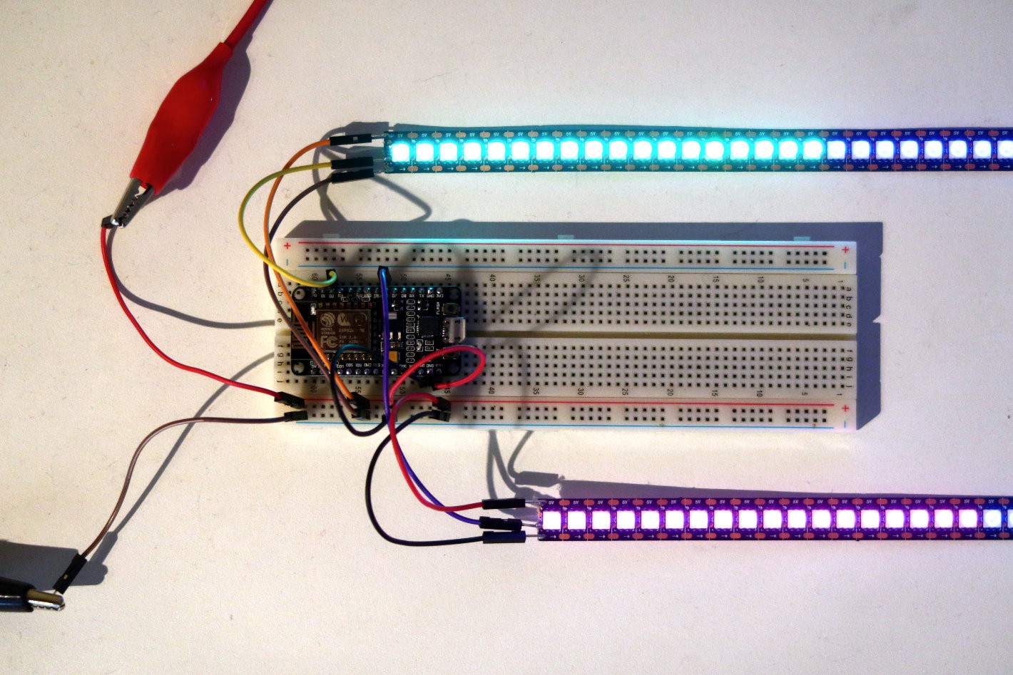
First of all, let's start with the electronics used for this project, which will be really simple since there are only two main components:
ESP8266:
I will use a development board with an ESP8266 to handle the WiFi connection to pull data from the internet. The ESP8266 will also directly drive the LED strip.
WS2813:
I have no particular reason to have chosen the WS2813 over some other LED strips such as the WS2812 or the APA102. My main requirement was to have a LED strip with 144 LEDs/m to ensure the clock will not become too large.

Lighting some LEDs was a piece of cake with the Adafruit Neopixel library.
A note about level shifting: strictly speaking I would need to transform the 3.3V signal from the ESP8266 to a 5V signal for the LED strip. However, because of the fast timing not every level shifter works. The ones I had lying around did in fact nothing at all to the voltage when I measured it. The internet recommends for instance a 74HCT245 level shifter, but I did not have this one available. Based on some encouraging comments on this Hackaday post I decided to skip the level shifter altogether, and that seems to be working fine so far 👍.
Designing the Frame
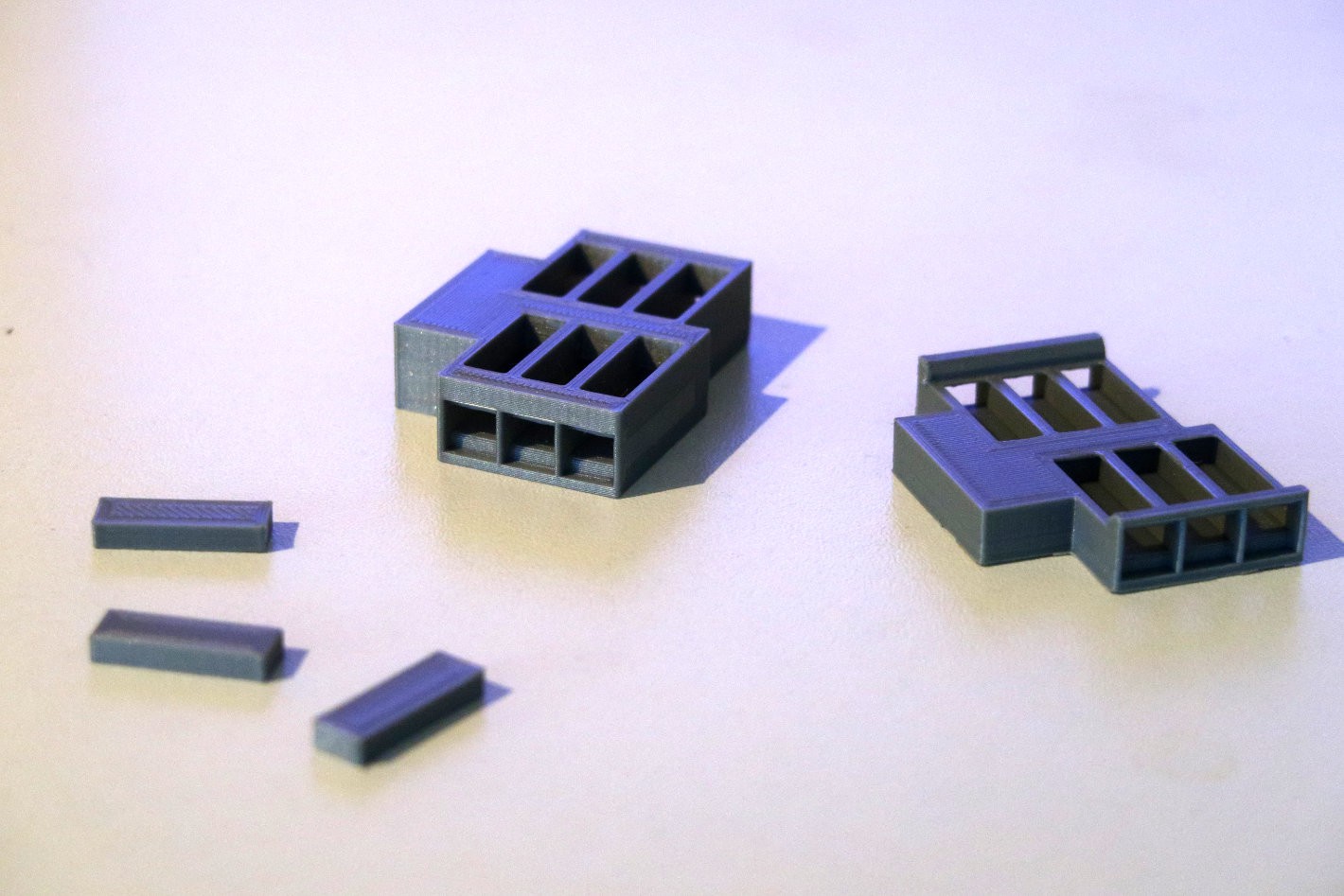
You can read here about the light guides I designed for this clock. I wanted to design a frame to hold all these little pieces in place directly behind the front panel. But as it turned out there was an issue with that. The LEDs on the strip are 5x5mm, but the strip itself is actually 12mm wide. Because of that there is roughly 2.5mm of strip that extends beyond the front. To not complicate the housing too much I decided to put the light guides further back in the housing and came up with the following prototype parts:

First prototype on the left, improved version on the right. The small pieces are surrogate light guides while waiting for my laser cut parts.
In the first design I simply made the housing thicker before the slot for the light guides. I did not think of it at first, but the main problem with this approach is the viewing angle. When you would look at the clock from the side with this design, you would look at the walls of the frame, and not see the numbers themselves. Because of this I made a second revision where I made the frame in front of the light guides as thin as possible.

The first large part I printed on my 3D printer with a length of 35cm. I needed the entire bed length of the bed. Diagonally.
Assembly
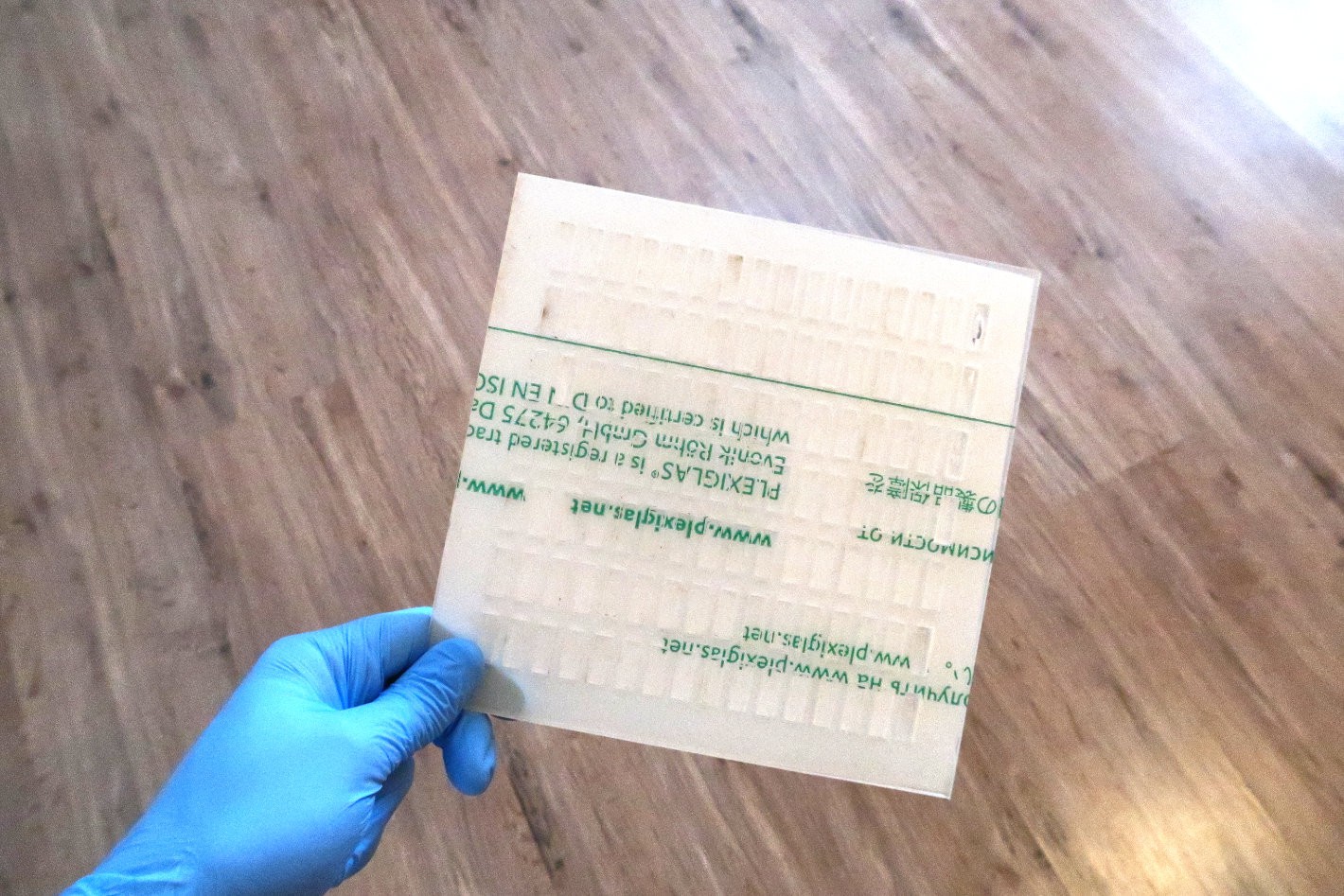
The good news is that in the mean time I received my laser cut parts, so I could immediately start the assembly by inserting the 97 small light guides into the frame. The fit was perfect, if anyting some of the slots were a little bit too snug 😇, but I managed to get them all in place.


The gloves are there to prevent fingerprints which might impact the quality of the lighting.
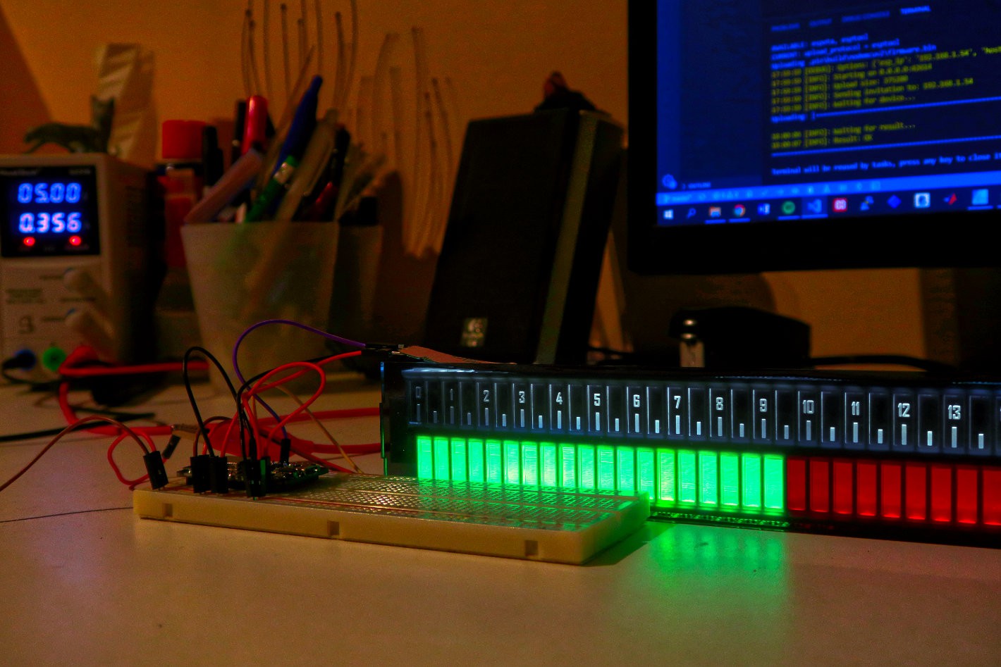
In the end the frame worked out great. Below you can see the frame in action for the first time with the LED strip just laying on top. In the next posts I will finish the assembly with the full housing, and start working on the software. I alread have quite some ideas of displaying different kinds of data with this display:
- The time
- Calendar or schedule
- Weather information
- Night, daylight sunrise and sunset
- Hourly stock gains and losses
- If you have any other cool ideas don't hesitate to tell me!

It's already starting to look awesome.
 Maakbaas
Discussions
Become a Hackaday.io Member
Create an account to leave a comment. Already have an account? Log In.