For the final log on the clock I will go into more detail on the software side. First I will briefly discuss the software architecture. Then I will explain the different display modes I developed so far. All code can be found on the GitHub repository for this clock.
Since the name of this project is the 'linear calendar clock', the calendar mode was the priority to implement 🙂. After some struggling I managed to implement the Google API as you can see in the animation below. I decided to split up the software in a part that is running on the ESP8266 itself, and another part that is running on a server to pre-process the data.
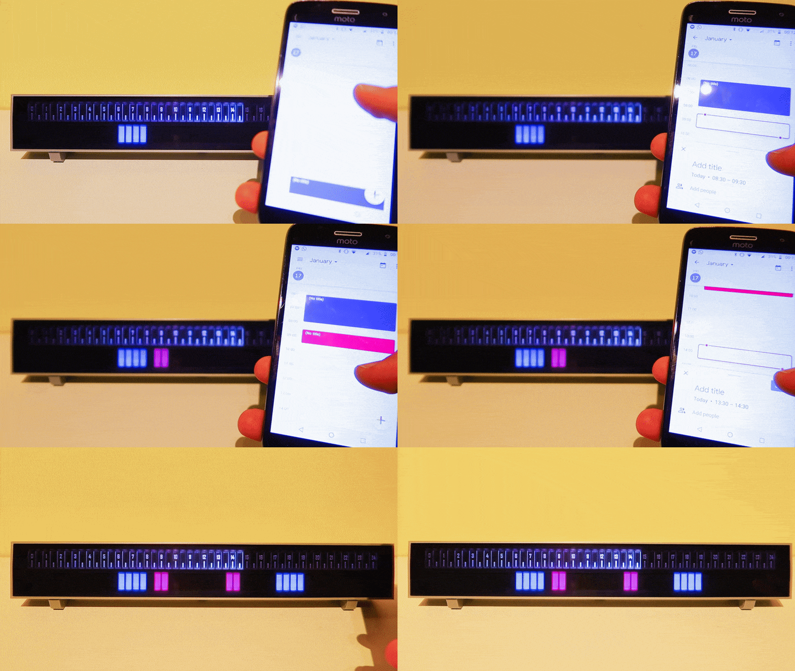
The Google calendar link in action
The software running on the ESP8266 is based on a template I developed for previous projects. Basically what the template implements is a Wifi connection and a web server. If the ESP8266 is not able to connect to a WiFi network, it will start a hotspot. If you connect to this hotspot from an external device you can set the WiFi details in a web page, which will then be stored into EEPROM and used during the next boot.
On top of this the ESP8266 implements the https request functionality to request from the internet what data to display. The Adafruit neopixel library is used to drive the LEDs. The data to be displayed is coming from endpoints that I wrote in Node.js to run as a Netlify function, since this can be used for free and I used Netlify already to host my website as well. You can see an example of how the code would work below.
var moment = require('moment');

var offset = 0;

exports.handler = async (event, context) => {
    const resp = moment.utc()
                       .add(1,'hour')
                       .format('HHmm');
    return {
            statusCode: 200,
            body: resp
    };
};
The Node.js endpoint serving the time in the correct timezone to the ESP8266
The time will be output as a 4 number string containing the hours and the minutes. So far I did not yet implement a clock functionality in the ESP8266, which would of course be perfectly possible. I could also have used a RTC as a back-up, but instead I opted to keep the setup as simple as possible and just request the new time periodically. That would look something like this:
http.begin(client_ssl, request_url);

String payload;
if (http.GET() == HTTP_CODE_OK)
{
    payload = http.getString();
    int hours = payload.substring(0, 2).toInt();
    int minutes = payload.substring(2, 4).toInt();

    float floatHours = (hours + (float)minutes / 60) * 2;

    for (int i = 0; i < NUMBLOCKS; i++)    {
        if (i + 1 <= floatHours)
            blocks.setPixelColor(i, blocks.Color(30, 30, 0));
        else if (i + 1 == ceil(floatHours) && minutes % 30 >= 15)
            blocks.setPixelColor(i, blocks.Color(60, 30, 0));
        else
            blocks.setPixelColor(i, blocks.Color(0, 0, 0));
    }

    blocks.show();
}
The ESP8266 code to read the time from the endpoint and display it on the clock
This code reads in the string from the endpoint and transforms it into a number to know which bars should be lighted, and which shouldn't for the normal clock mode.
Normal clock mode
In the normal clock mode, the bars are lighted green to show the current time in half hours. In addition, if a quarter has passed, the last LED will show in yellow. This can also be seen in the code example above. I could probably have implemented more colors, or rules to be able to read the time even more granular, but that would be beside the point for this clock, and make reading the time less intuitive.
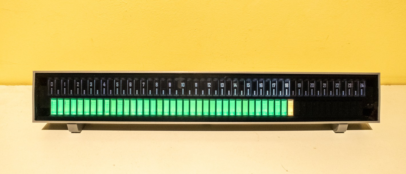
It's a quarter past six
Calendar mode
The highlight for me is the calendar display, which is in part what triggered me to design a linear clock like this. This Stackoverflow answer was a big help for me to implement the Google API in my endpoint. This was an area where I did not have any experience before. I also implemented support for multiple calendars to be able to show them in different colors. Baiscally the endpoint returns a 48 number string, with a 0 for no appointments, and a number corresponding to the different calendars for busy time slots. As with everything the final code can be found in my GitHub repo.
In calendar mode the actual time is shown in the top half of the clock. The tick marks have increasing brightness up to the current time. After that they are shown a bit darker again. Until now this is the best balance between aesthetics and functionality I found.
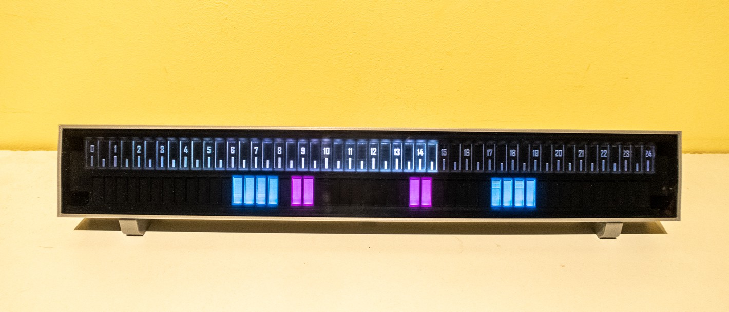
It is half past two and my next appointment is still more than two hours away
Rainbow clock mode
In this mode the time is also deducted from the number of lighted blocks, but what better way to show off RGB LEDs than to display a rainbow 🌈? To do this the ColorHSV function is used. With this it is quite easy to make a color gradient. Behind the scenes the Neopixel library will convert this back to RGB values. The same time endpoint is used, only the processing in the ESP8266 is different.
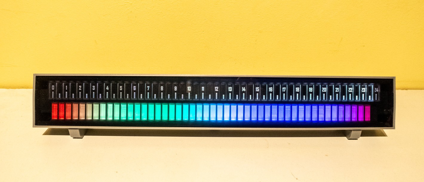
It is 23:30, the most beautiful time of the day
Daylight display mode
In this mode the clock bars show astrological, nautical and civil twilight to tell you exactly the day and nighttime for the current day. In addition the time ticks will light up in different colors to show the actual time. If the actual time is at night the ticks will be shown in white, if the actual time is during the day the ticks will have the color of the sun, becoming more orange and pink when the time is during sunrise and sunset. The endpoint for this display is implemented using the API from sunrise-sunset.org
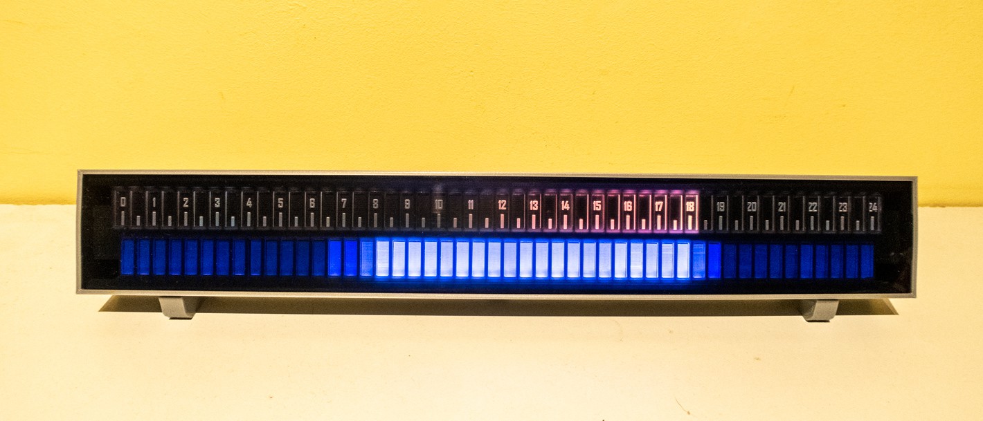
It is six o'clock, if you can't look outside, enjoy the little sunset on the clock
Goal tracking mode
Finally, the clock can also be used as a goal tracking display. I did not implement an endpoint for this yet since it will depend completely on which goal you want to track. Think of something like a saving goal from your budgetting app or the target number of steps from your fitness tracker. In this mode the display can not be used as a clock, and the numbers 1-24 will be hidden by disabling their LEDs. Also the display can be set up with different red, orange and green zones, depending on your targets.
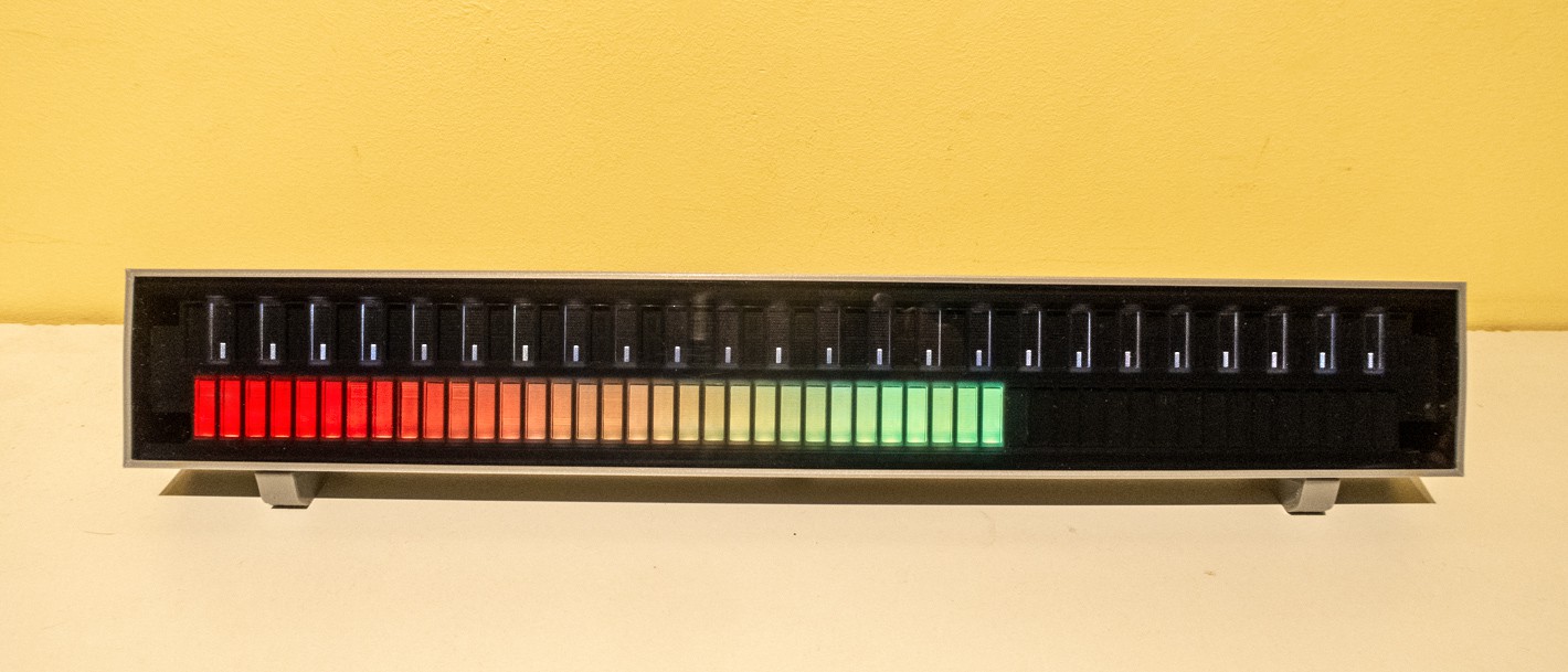
You're well on your way to meet your goal!
Wrap-up
Even though I could implement a number of other modes and enpoints, I consider the project finished for now ✅. Other ideas could be to show hourly stock gains and losses, or expected temperature or precipation. This would simply be a matter of writing a new endpoint and implementing the color strategy in the ESP8266. If you have any other ideas to improve the design, or if you have started to build your own, I'd be happy to learn about it!
 Maakbaas
Discussions
Become a Hackaday.io Member
Create an account to leave a comment. Already have an account? Log In.