 Ken Yap
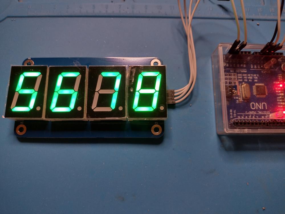
I had a couple of boards left over so about a year ago I ordered a batch of green inch high 7-segment displays to use up the boards and have a change from the boring red displays. They both have the same pinout. They duly arrived and I made up one board. But you know the familiar story, it didn't work when first powered up. I tried a few things then put it aside in frustration.
Last week, with more time on my hands, I decided to debug it once and for all. I connected it to an Uno and fired up my digit scrolling sketch which appears to shift digits to the left at 2 Hz (but of course it's actually periodically incrementing every digit by 1). Using a Hantek USB scope which I hadn't unpacked for a long time (another sad and familiar story) and the OpenHantek program, I found that the waveform on the clock line was high all the time except bursts of low going pulses at 2 Hz. On the data line, the bursts were absent but there was a large dip of the level at 2 Hz. Here is the part of the circuit:
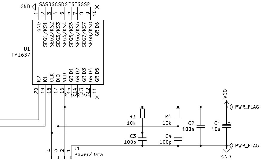
Since there weren't any multiplexing waveforms on the digit or segment lines, I decided that the TM1637 IC was faulty and decided to replace it. So I used the hot air gun to desolder it and then soldered in a new TM1637. Hah! Same fault. This time I figured that the only possiblity left was C4 being too high in value and obliterating the pulse train. Without the initialisation commands the IC probably didn't start multiplexing. C4 with R4 form a simple noise filter, so I desoldered C4, and the circuit starting working. So I replaced C4 with a new 100 pF capacitor. What happened? Who knows, maybe I picked up the wrong SMD component. Unlike SMD resistors, SMD capacitors have no value markings. I'll have to be careful to use the correct tape in future.
I put the extracted IC on the remaining board and that worked too. So now I have two more working displays.
Discussions
Become a Hackaday.io Member
Create an account to leave a comment. Already have an account? Log In.