Design
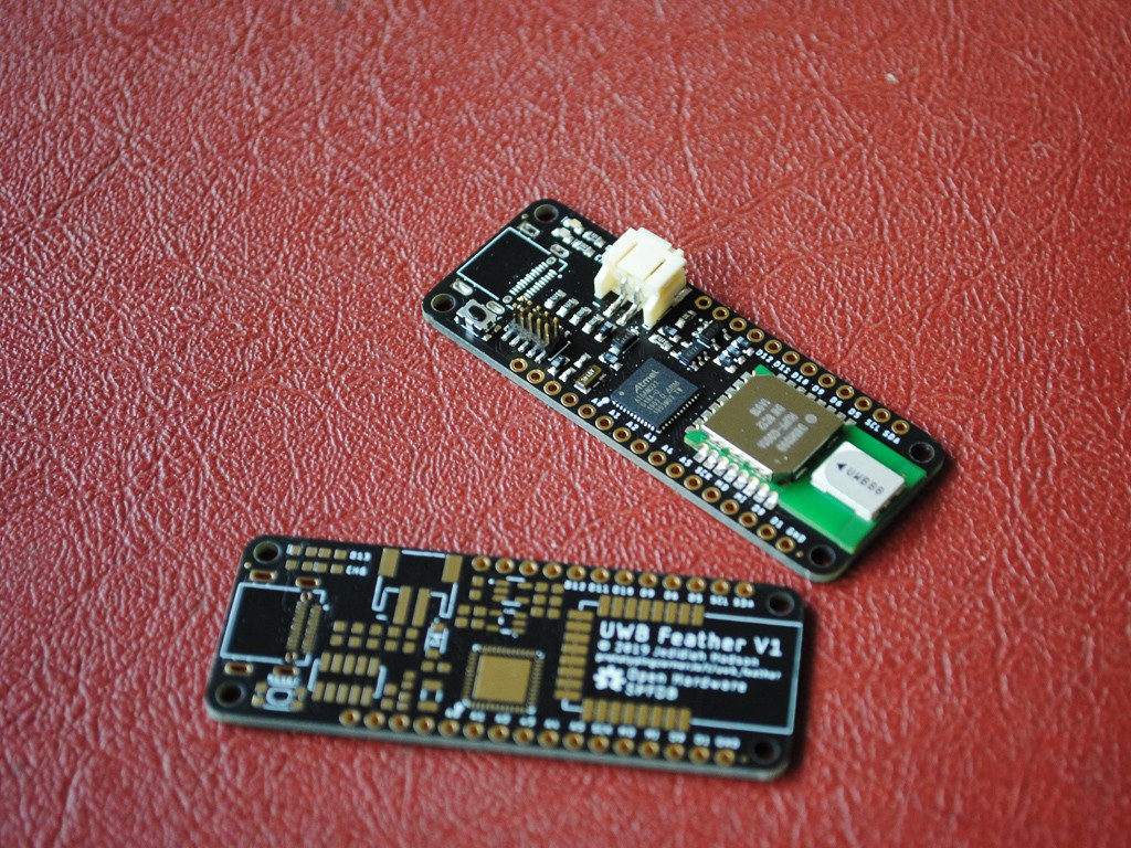
As mentioned in the introduction, the UWB Feather consists of an ATSAMD21 ARM Cortext M0+ for the brains and a Decawave DWM1000 module for the ultra-wide band wireless, in the feather form-factor. The design is relatively simple consisting of 20 BoM items on a 2-layer PCB. Pinout is Adafruit M0 Feather compatible
LiPo charging is handled by the MCP73831 single-cell, fully integrated charge management controller. Battery voltage can be monitored on D9, however is access to all the IO is required, JP1 can be cut to free up this pin. 3.3 volt regulation is preformed by the AP2112K-3.3 low dropout linear regulator, providing up to 600mA.
Pinout is fully compatible with the Adafruit M0 feather line for easy code portability. The DWM1000 IO lines are connected to the SPI bus and digital pins 2, 3 & 4 for RST, IRQ & SPI_CS respectivly (which are not exposed via the header). D13 is also connected to the onboard LED, as is standard among many Arduino-compatible boards.
Programming can be preformed over the SWD header or via USB if loaded with a corresponding bootloader such as the uf2-samdx1 from Microsoft. See firmware for more.

Note on V1.0: There is an issue with the USB-C connector on version 1 of this board. The footprint I used did not include the cutout required for the cutout mounting method of this component.
Version 1.1 will include a fix for this as well as adding a micro-b connector for those who want it. See version 1.1 considerations below.
The DWM1000 has a One Time Programmable (OTP) user programmable memory for storing calibration information (see 1.6 in the datasheet). To program this region the VDD3V3 pins may need to be raised to 3.8 volts temporarily. To do this JP2 can be cut and a separate power supply can be connected to selectively boost the power to the module.
Version 1 Board Renders


Bill of Materials
BoM items are all available from DigiKey and are plentiful in supply. Total BoM cost was $60 AUD for 1 quantity, however further optimization can shave a few dollars off this.
CSV version of this table can be found in the project repository.
| Manufacturer Part Number | Manufacturer | Digi-Key Part Number | Customer Reference | Quantity | Description |
|---|---|---|---|---|---|
| DX07B024JJ3R1600 | JAE Electronics | 670-2963-1-ND | J1 | 1 | CONN RCP USB3.1 TYPEC 24P SMD RA |
| S2B-PH-SM4-TB(LF)(SN) | JST Sales America Inc. | 455-1749-1-ND | CN1 | 1 | CONN HEADER SMD R/A 2POS 2MM |
| KMR241GLFS | C&K | 401-1431-1-ND | SW1 | 1 | SWITCH TACTILE SPST-NO 0.05A 32V |
| AP2112K-3.3TRG1 | Diodes Incorporated | AP2112K-3.3TRG1DICT-ND | U4 | 1 | IC REG LINEAR 3.3V 600MA SOT25 |
| MBR120VLSFT1G | ON Semiconductor | MBR120VLSFT1GOSCT-ND | D2 | 1 | DIODE SCHOTTKY 20V 1A SOD123FL |
| ATSAMD21G18A-MU | Microchip Technology | ATSAMD21G18A-MU-ND | U1 | 1 | IC MCU 32BIT 256KB FLASH 48QFN |
| 20021221-00010C4LF | Amphenol ICC (FCI) | 609-3700-1-ND | J4 | 1 | CONN HEADER SMD 10POS 1.27MM |
| DWM1000 | Decawave Limited | 1479-1002-1-ND | U3 | 1 | RF TXRX MODULE 802.15.4 CHIP ANT |
| MCP73831T-2ATI/OT | Microchip Technology | MCP73831T-2ATI/OTCT-ND | U2 | 1 | IC CONTROLLR LI-ION 4.2V SOT23-5 |
| RC0603FR-075K1L | Yageo | 311-5.10KHRCT-ND | R1, R2, R6 | 3 | RES SMD 5.1K OHM 1% 1/10W 0603 |
| SML-D12D8WT86 | Rohm Semiconductor | 511-1577-1-ND | D1 | 1 | LED ORANGE DIFFUSED 0603 SMD |
| 150060BS55040 | Würth Elektronik | 732-12013-1-ND | D5 | 1 | LED BLUE DIFFUSED 0603 SMD |
| RC0603FR-071KL | Yageo | 311-1.00KHRCT-ND | R4 | 1 | RES SMD 1K OHM 1% 1/10W 0603 |
| RC0603FR-07100KL | Yageo | 311-100KHRCT-ND | R5, R3 | 2 | RES SMD 100K OHM 1% 1/10W 0603 |
| TMCJ0J106MTRF | Vishay Sprague | 718-2355-1-ND | C5, C7, C8 | 3 | CAP TANT 10UF 20% 6.3V 0603 |
| RC0603FR-0710KL | Yageo | 311-10.0KHRCT-ND | R10 | 1 | RES SMD 10K OHM 1% 1/10W 0603 |
| TMCJ1C105MTRF | Vishay Sprague | 718-2362-1-ND | C1, C4, C6, C9 | 4 | CAP TANT 1UF 20% 16V 0603 |
| RC0603FR-07330RL | Yageo | 311-330HRCT-ND | R9 | 1 | RES SMD 330 OHM 1% 1/10W 0603 |
| CC0402FRNPO9BN150 | Yageo | 311-1642-1-ND | C2, C3 | 2 | CAP CER 15PF 50V C0G/NPO 0402 |
| FC-135 32.7680KA-A0 | EPSON | SER4077CT-ND | Y1 | 1 | CRYSTAL 32.7680KHZ 12.5PF SMT |
Hardware Version 1.1 Considerations
There are a number of changes required for a board that would be put into production as nobody gets it right the first time, every time. So here’s a list of changes required:
- Change the USB-C connector BoM item and PCB footprint
- Add Micro USB footprint in addition to USB-C (makers choice)
- Replace individual charge and D13 LED’s with RGB led to integrate
- Change SWD 5×2 header BoM item
- Add pull-up resistor on DWM1000 IRQ line
- Reroute with 8/8 mil minimum traces
- Tidy up silkscreen layer
- Enlarge test pads and expose SWD on bottom layer for pogo-pin programming
- Re-position crystal and bypass capacitors to be closer to target components
- Pullback copper fill and wires from the antenna facing side of DWM1000 module
- Change J4 (SWD header) BoM item
Assembly
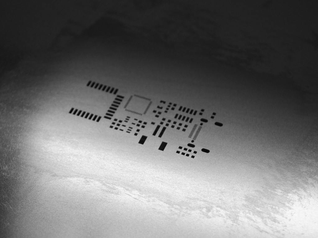
With only 20 BoM items and most components being no smaller than 0603 (the 2x crystal capacitors were 0402) , hand assembly of this board was easy. I had the PCB and solder stencil manufactured by JLCPCB in matte black with ENIG surface finish.
Total cost for 5 boards (although 10 had no price difference) and stencil was $68 AUD, however $42 of that was shipping. First time ordering from JLCPCB and boards were of very high quality with nice finish.
Firmware
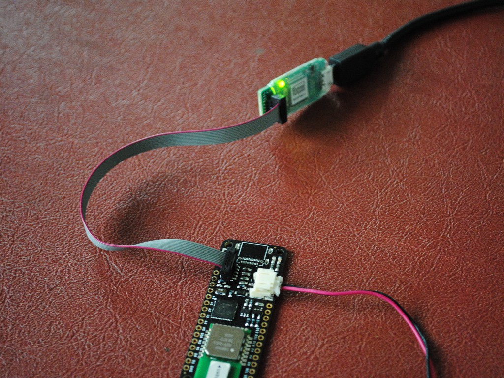
Firmware can be loaded over the SWD connector using a programmer such as the J-Link from Segger. Shown above is the J-Link EDU Mini. To start programming the board, we need to load our bootloader then set up our tool chain.
Programming the bootloader
I’ll be using Atmel Studio for flashing the bootloader. To do so, plug in the J-Link and open Atmel Studio. Then select Tools > Device Programming. Under Tool select the J-Link and set Device to ATSAMD21G18A then click Apply.
Connect the J-Link to the feather SWD header and apply power either over USB or via the battery. Once connected, under Device Signature click Read. The Device Signature and Target Voltage text boxes should propagate accordingly. If they do not check the connections and try again.
To flash the bootloader we first need to disable the BOOTPROT fuse. To do this select Fuses > USER_WORD_0.NVMCTRL_BOOTPROT and change to 0 Bytes. Click Program to upload the changes.
Now we can flash the bootloader by selecting Memories > Flash and set the location of the bootloader. Ensure Erase Flash before programming is selected and click Program. If all goes well D13 on the board should begin to pulse.
Now you’ll need to set the BOOTPROT fuse to the 8kB bootloader size. To do this select Fuses > USER_WORD_0.NVMCTRL_BOOTPROT and change to 8192 Bytes. Click program to upload the changes.
Now that the bootloader has been flashed D13 should be pulsing and if plugged in over USB, a mass storage device should appear. This is where UF2 files can be uploaded for programming the board.
Flashing firmware with PlatformIO

Firmware can be uploaded over the UF2 protocol or directly via the SWD interface. Here we’ll be using PlatformIO for its ease and simplicity. To get started create a new PIO project and select Adafruit Feather M0 as the target board. When uploading over SWD with a J-Link set the upload_protocol in platformio.ini as shown below.
[env:adafruit_feather_m0]
platform = atmelsam
board = adafruit_feather_m0
framework = arduino
upload_protocol = jlink
Now you can program the board with the simplicity of the Arduino framework.
Flashing the Anchor
The DWM1000 modules can be configured to be anchors or tags. Generally anchors are kept at known static locations and tags use anchors to get a relative position to them. To test the DWM1000 module you can upload the DW1000-Anchor example from the GitHub repository.
To flash this program with PlatformIO, from PIO Home, select Open Project then find the location of the DW1000-Anchor folder in the GitHub repository. Then click the PIO upload button and it will automagically find the attached debug probe (ensure it is connected and the board is powered).

The tag firmware will need to be uploaded to another board. Then the result can be viewed in a serial terminal.

Going further
Further improvements to this project will include development on a new DW1000 library, V1.1 board changes other projects that utilize this ranging technology. If there is sufficient interest I will consider manufacturing and selling these boards.
Thanks for reading. Leave any thoughts or criticisms in the comments below.