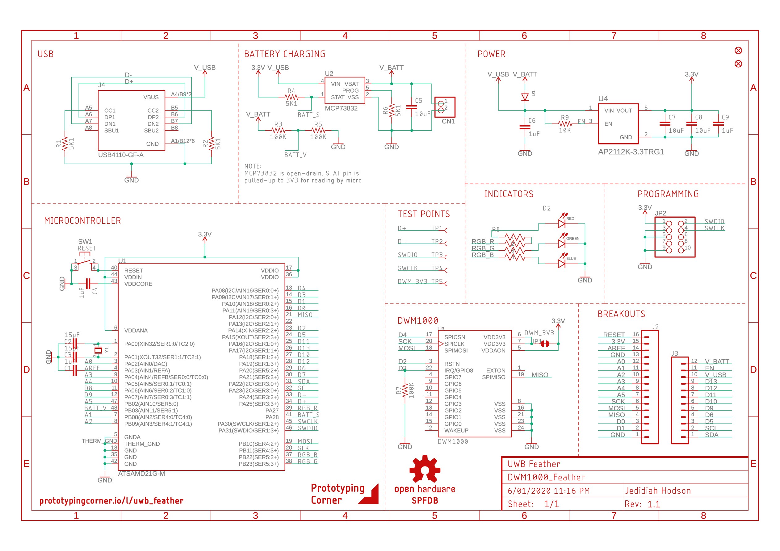
Schematic for Version 1.1. Issues with first boards fixed and I took the opportunity to make a few other changes. The board file is still incomplete (fully routed, just needs a little tidying up) and I need to update the BOM - will finalize tomorrow.
Changes:
- Changed USB-C connector
- Added pull-up resistor on DWM1000 IRQ line
- Rerouted with larger trace widths (10mil)
- Enlarged test point footprint and changed exposed pins: USB D+ and D- instead of CC1&2, removed D2, D3 and replaced with SWD for programming
- Reduced wire protrusion around antenna
- Replaced D13 and charge indicator for RGB led and connected to unused pins on M0
- Changed the charge controller from MCP73831 to the MCP73832 and connected the STAT pin to an unused pin on the M0. Now it is possible to detect when the battery is charging in software however controlling the charge LED (RGB LED) will need to be done in software.
- Connected BATT_V to unused analog pin (instead of D9)
What these changes mean:
- The USB-C connector will actually fit on the board.
- Board is now better suited to going in a test jig.
- All exposed header pins are fully available IO (no shared lines)
- There's an RGB LED and charge detection is now more flexible.
Changes to the pins will mean I will need to create a custom bootloader based off UF2, however I am much more happy with the board design and its flexibility. Intermediate changes are in the GitHub repo under the version-1.1 branch.
Discussions
Become a Hackaday.io Member
Create an account to leave a comment. Already have an account? Log In.