I had been working on the artwork behavior, assets, and software in parallel with the hardware. The overall architecture that I ended up with is this:
- Cython language--it's Python with a little extra static typing that is compiled as C, for dramatically faster performance in many cases
- Multiprocess architecture. By splitting blocking tasks into different processes I could arrange for much higher overall framerate
- The Python-IS31FL3733 driver (GitHub) is fairly primitive and performs best updating an entire display at once.
- Key processes:
- Launcher that monitors individual processes and restarts them if they die. It handles logging, pyximport (Cython magic), provides a message bus via Multiprocessing Queue and Pipe interfaces, and handles overall process control for graceful shutdowns
- Main application process, RoadAhead.
- Children: Renderers. At any given moment there are two renderers active out of an overall selection of 6 or so. They each render into a Pygame surface. The application process switches renderers, and alpha-blends the two active renderers together based on an overall "temperature" variable
- Pipe in: Render request
- Queue in/out: System bus
- SurfaceToRad renderer. Turns Pygame surfaces into the raw byte list (16x12 8-bit) required by Python-IS31FL3733.
- Pipe out: RadDisplay
- RadDisplay process. Initializes Python-IS31FL3733 i2c drivers for each display, restarts each if connection is lost. Emits "Render" requests as each frame is rendered. Maintains a 10-frame buffer (yes this is long, the artwork's responses to sensors are not intended to be that fast/readily triggerable. Think of it as a skittish cat. It will do what it wants on its own time and you are not intended to be able to directly control it)
- Pipe in: SurfaceToRad
- Pipe out: Render request
- Queue out/out: System bus
- RadGpio. Monitor select pins for GPIO events triggered by PIR and RCWL-0516 microwave sensors. Emit system bus events when they occur.
- Queue out/out: System bus
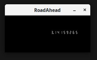
- Not a process exactly, but I needed to develop each of these components before the hardware was ready, so there is also a Pygame "simulator" environment that runs on my banged-up Ubuntu-powered Dell Latitude. (Best $150 I ever spent.) It deteects
One interesting problem was transforming these 7-segment displays into a general purpose pixel display. Under the hood the artwork considers itself to have a full pixel surface available at its disposal. It samples select pixels, calculated to match the physical position of each LED segment, and averages 2x2 pixel bins to get the desired grayscale value for each LED segment. This is somewhat computationally expensive, which is part of why I derived some benefit from pushing that into its own process (SurfaceToRad) on the multi-core Pi 3.
So once I went to all that effort to make a 7-segment display into a graphic display... then I wanted to show numeric digits back on the display. That's part of the fun to me, to have these numbers suddenly morph into a graphic display after you've been watching the numbers for a few moments--ideally in a mini galaxy brain moment (hey, gotta aim big). I ended up just working backwards from the SurfaceToRad logic: identify the pixels that will be used later as "ingredients" for each segment's brightness, then set each of those pixels to the desired brightness.
Here's what that looks like in the simulator.

You might be wondering by now: what exactly does this artwork do and why does it do it? It's risky to go too far down the road of explaining your own art--risky because you run the risk of constraining how your viewers will perceive and interact with the work. So bear with me for a moment if this explanation doesn't line up with your take:
I am interested in how huge numbers of people are reduced to abstract numbers, often for the purpose of communicating about them in detached, alienating ways.
I thought it would be interesting to flip that dynamic--personal becoming impersonal through numbers--and use numbers as ingredients in a more personal or evocative visual display.
First, it starts by just showing you numbers, some meaningful, some meaningless. They are shown in a variety of ways, including some that appear like sums or subtraction, some reports, some dramatic single figures, some streams of endless digits.
Then the scene that you see once the artwork decides you're ready (by sensing enough motion) is an endless road (my homage to a certain bus-themed video game). As it senses movement to either side of the piece, hitchhikers appear in this landscape, but you never stop to pick them up. It will eventually fade back to the number-based displays.
Direct? no. controllable, puppet-style? no. but hey, that's what makes art fun to think about--making it chewy by layering all this extra stuff into it. imho, of course :)
Once I had the panels together I was really itching to get a prototype version of it out where I could gauge how people were interacting with it.
The artwork has several motion sensors in it, which guide the overall "temperature" variable, used to determine which view is shown. I felt that I couldn't really tune the sensor/temperature response until I could better see how patient casual viewers would be.
So speaking of galaxy brain, I had my own such moment when I realized that I had designed a 5v i2c system and utterly failed to account for how a 3v3 Raspberry Pi would communicate with it.
I had about two days before this totally great open-hang art gallery event--"1460 Wall Mountables" at the DC Art Center (you show up with $20 or so and can literally hang anything you want--one year I hung a horseshoe crab shell and sold it for $40). I was dyyyying to hang this artwork in the show. And of course my available inventory of level converters was 0 units. So, here's the dumb fix I came up with:
Use an XL6009 to bring the panel supply voltage of 5v down to 4v. Then it'll detect the ~3v signals from the Pi as high!
Added advantage of reducing system heat emission, and because the is31fl3733 is current-controlled, I don't think I lost any brightness from doing this.
I needed an enclosure. The DC Public Library has a laser cutter available, but it wasn't available right then because the library was being renovated. So I hit up (now sadly defunct) makerspace Catylator in Silver Spring and lasered me some 3mm plywood.
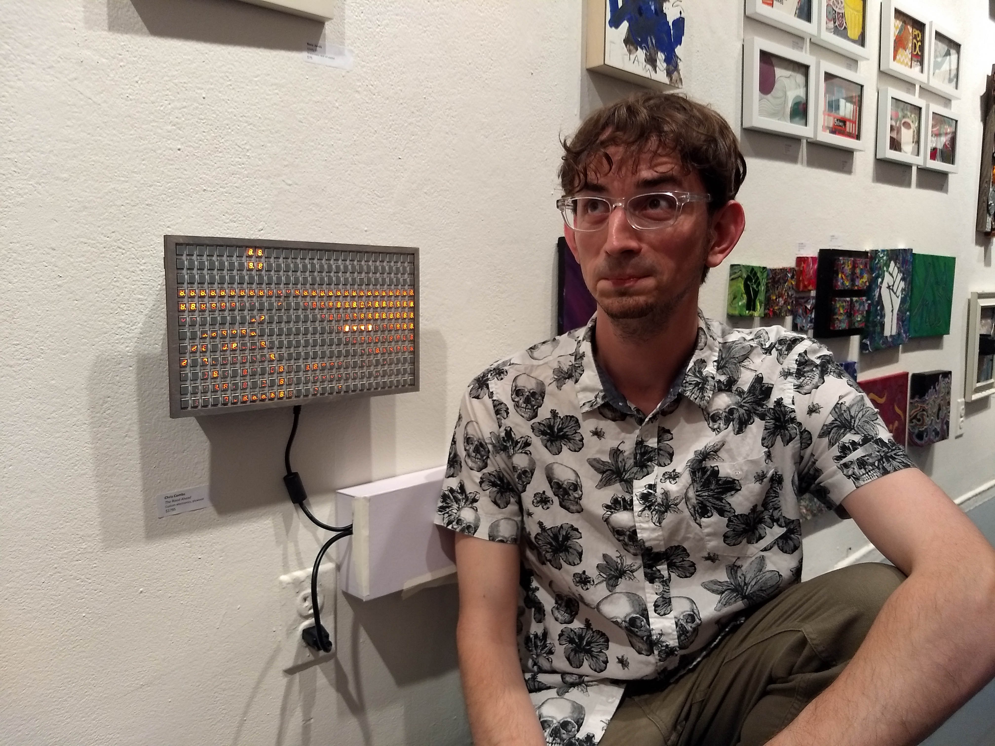
A bit of gray stain later, some bibs and bobs, and voila, prototype version (pardon my ridiculous face, someday I'll learn):

 Chris Combs
Discussions
Become a Hackaday.io Member
Create an account to leave a comment. Already have an account? Log In.