 John Anderson
Now I needed to figure out how to install the new input switches and button. I started by laying out a faceplate design to scale using the open source drawing software Inkscape on my PC. I set it up to use mm for the scale.
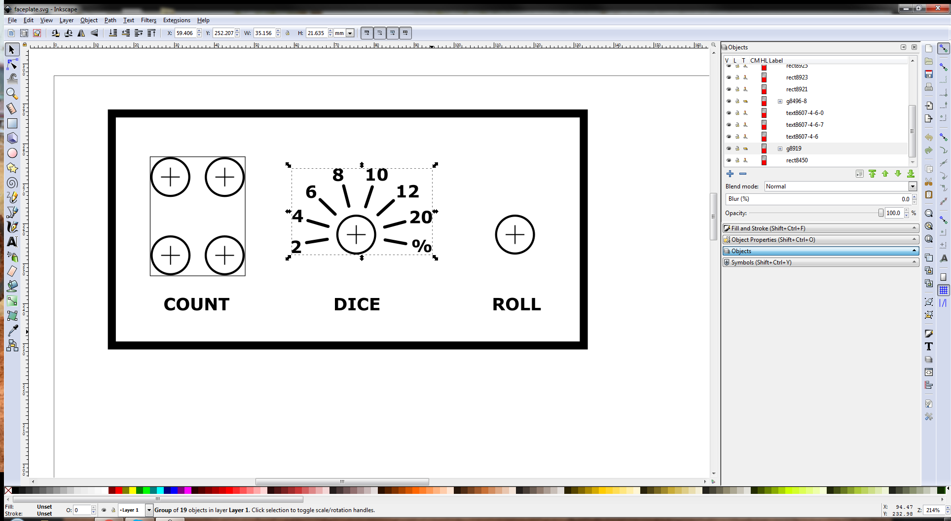
I then printed this to paper and cut it out. Using it as a template, I cut a piece of 1/16th inch aluminum. Note, I put painter's tape on the face of the aluminum plate before working with it. This prevents it from getting scratched up while cutting, filing, and drilling on it.
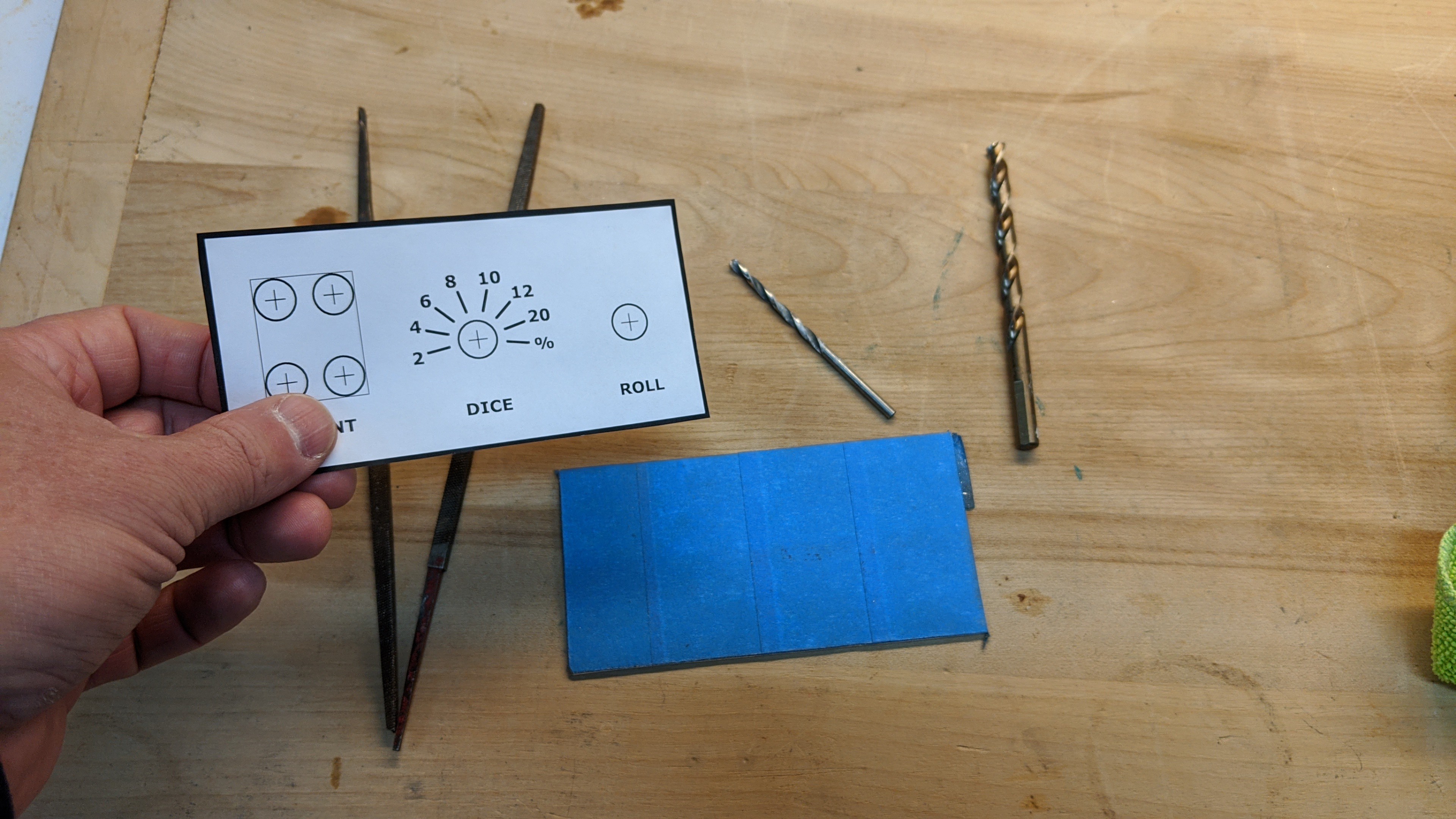
I then taped the paper cutout I printed earlier to the front of the aluminum plate. It'll be the template to drill the holes to mount the button, rotary switch, and thumbwheel.
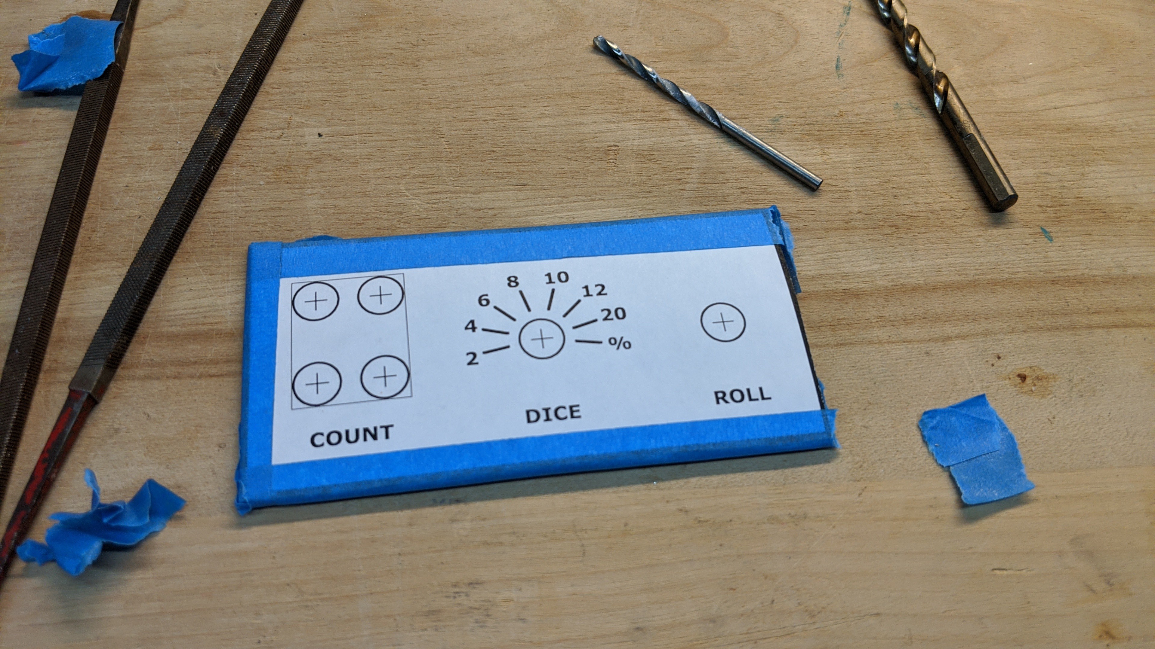
Then I drilled the six holes as they were marked in the template. To get the square hole to mount the thumbwheel, I used one of the small square files pictured and squared the sides of the drilled holes. I then took a jigsaw with a metal cutting blade and connected the four holes along the outer lines marked by the template. I was very careful not to cut or file beyond the thin line marking the rectangle. If I didn't cut enough with the jig saw, I cleaned up with the files until the switch fit nicely.
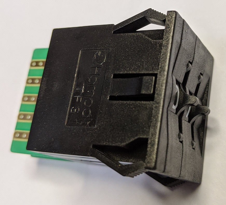
Notice that the switch has a small 1 mm bezel around it. This will hid the small imperfections of the square hole I made with the drill, files, and jigsaw. Unfortunately, I don't have a picture of it.
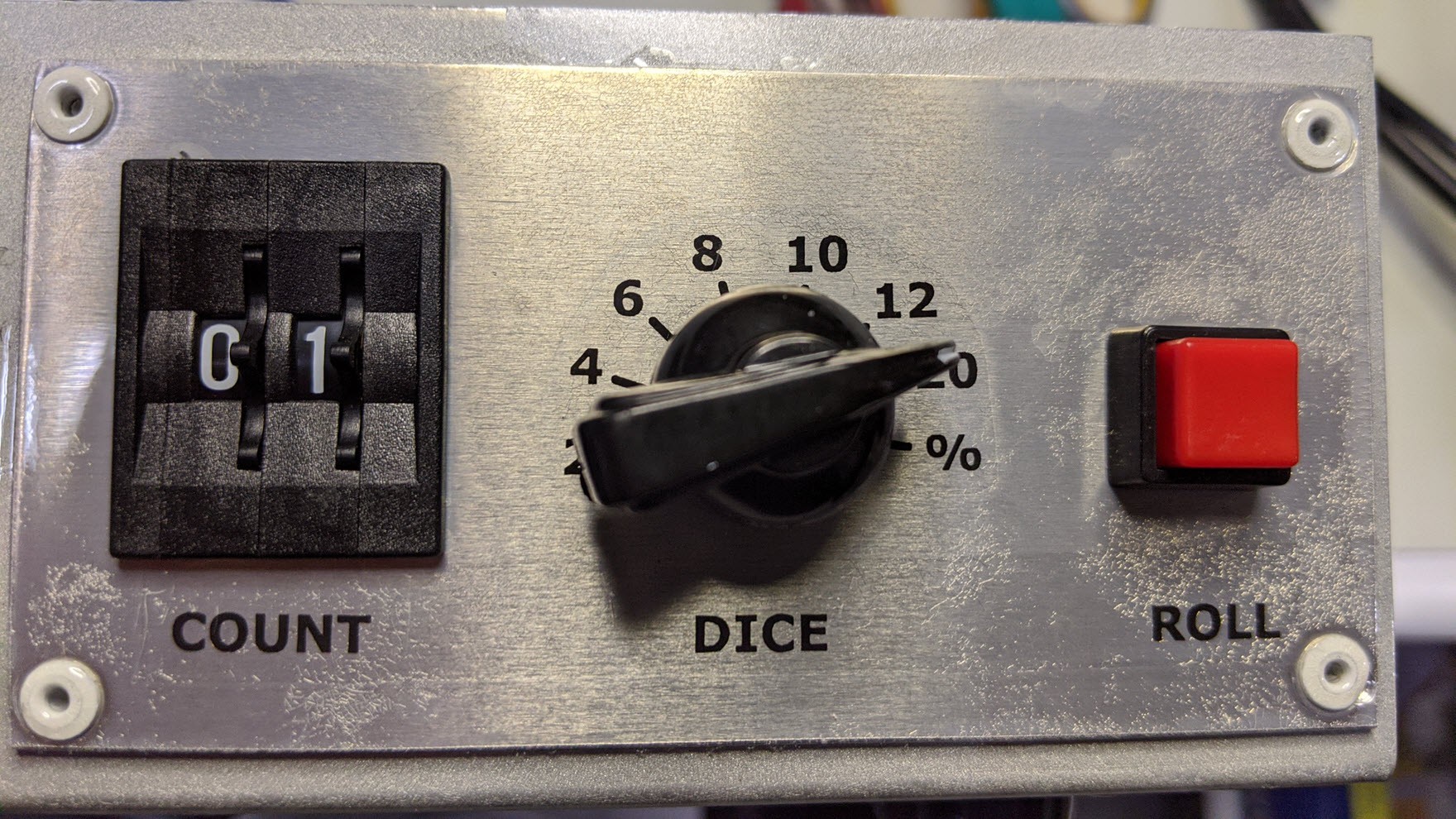
Lastly, I took the drill and jigsaw and cut the larger rectangular hole in the front faceplate of the case there the original switched and connectors were located. This rectangle was roughly 10 mm smaller than the faceplate I just made. I then positioned the new faceplate on the front of the case and drilled four 1/16" holes in the corners through the case and riveted it to the case. Here's how it looks installed with the new switches.
Discussions
Become a Hackaday.io Member
Create an account to leave a comment. Already have an account? Log In.