 John Anderson
To keep this project looking the part, I selected input hardware technology that dates back to the period. This includes a panel mount momentary push button to roll the dice, a 8 way rotary switch to select the die type, and a 2 digit 10 position decimal thumbwheel switch to select the number of dice. I covered how these were physically installed into the case in a previous log. In this log, I'll describe how they were wired up to the AVR microcontroller.
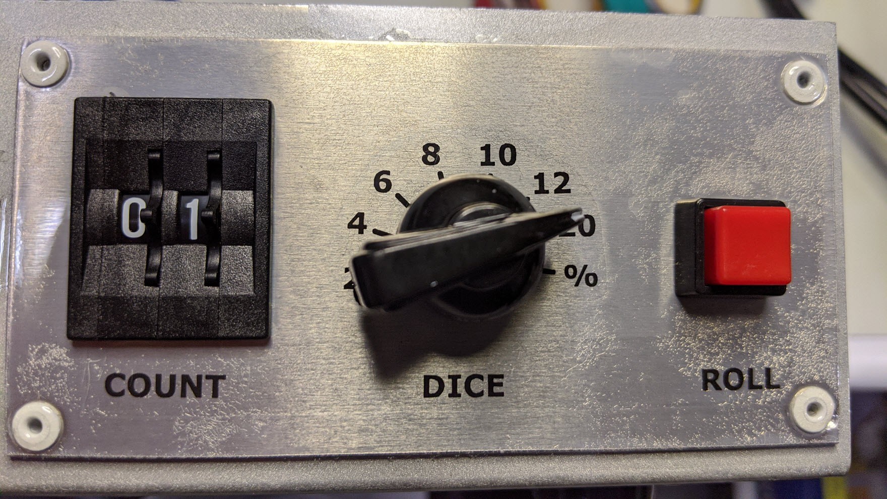
The button is a simple connection to one of the AVR pins configured as an digital input with the pull up enabled. The other side of the switch is connected to a common ground with the AVR. It connects to the controller board via a keyed 2 pin single row IDC connector.
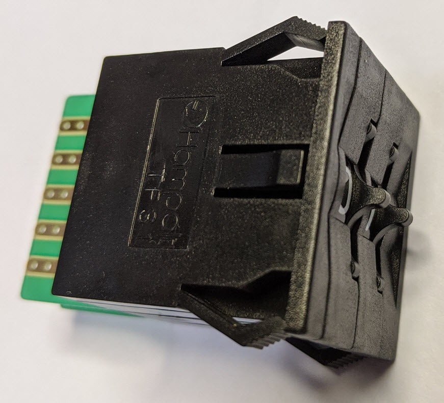
The 2 digit decimal thumbwheel switch is a Hampolt TF31 2-Digit Thumbwheel Switch (BCD encoded). These can be found on E-bay for a reasonable price. They ship from Taiwan so plan for a lead time of a week or two. If you substitute another thumbwheel switch, be sure to get a BCD encoded style switch to minimize the number of processor inputs or external logic IC's required. I soldered a short piece of multi-color 10 conductor flat ribbon cable directly to the pads and crimped on a 10 pin dual row female IDC connector on the other end to connect to the controller board. Like the button, the 8 AVR pins are configured as digital inputs with the pull-ups enabled. The cable to the switch includes ground which is connected to the common pad on both digits.
The rotary switch is an 8 position single deck unit.
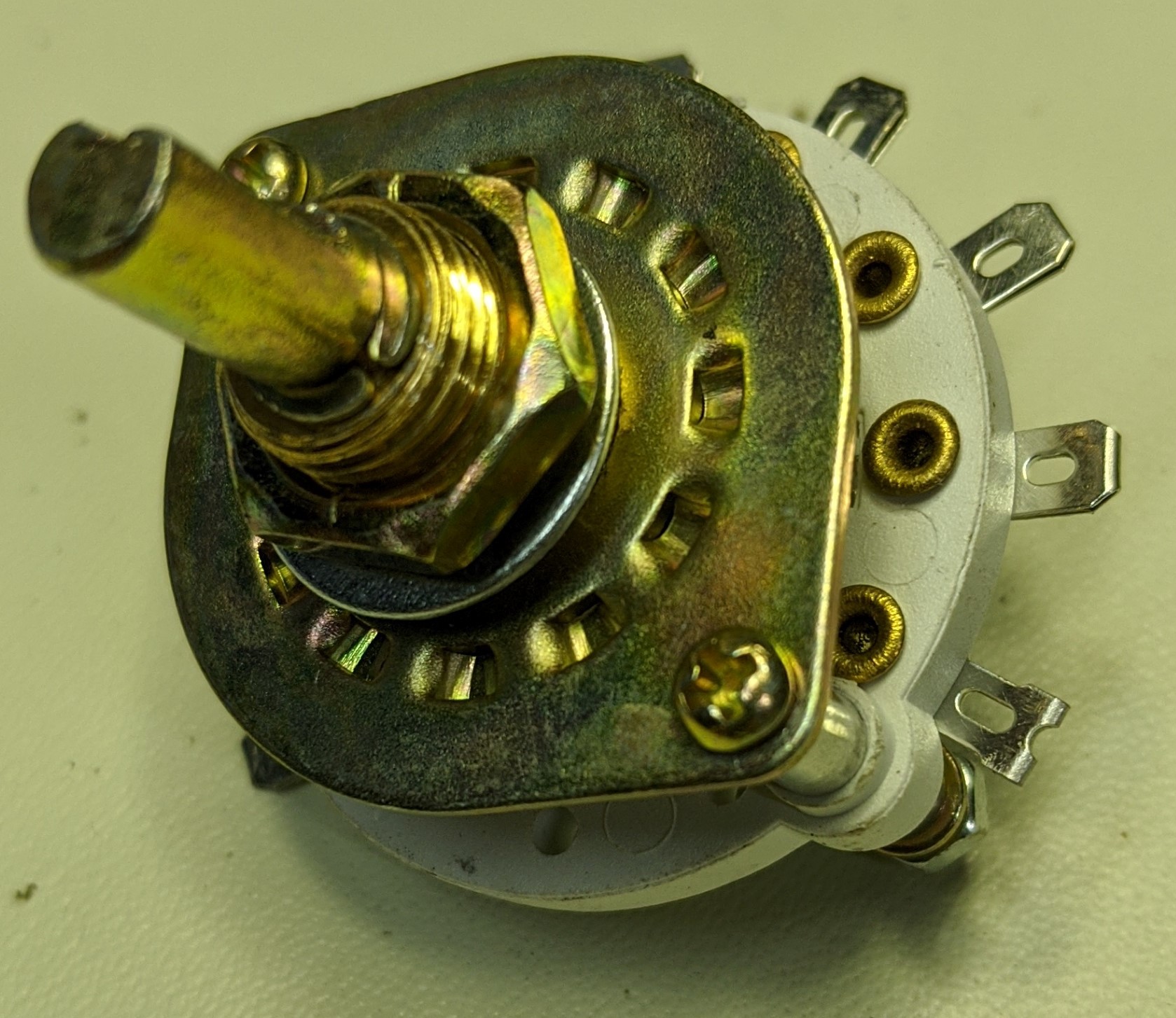
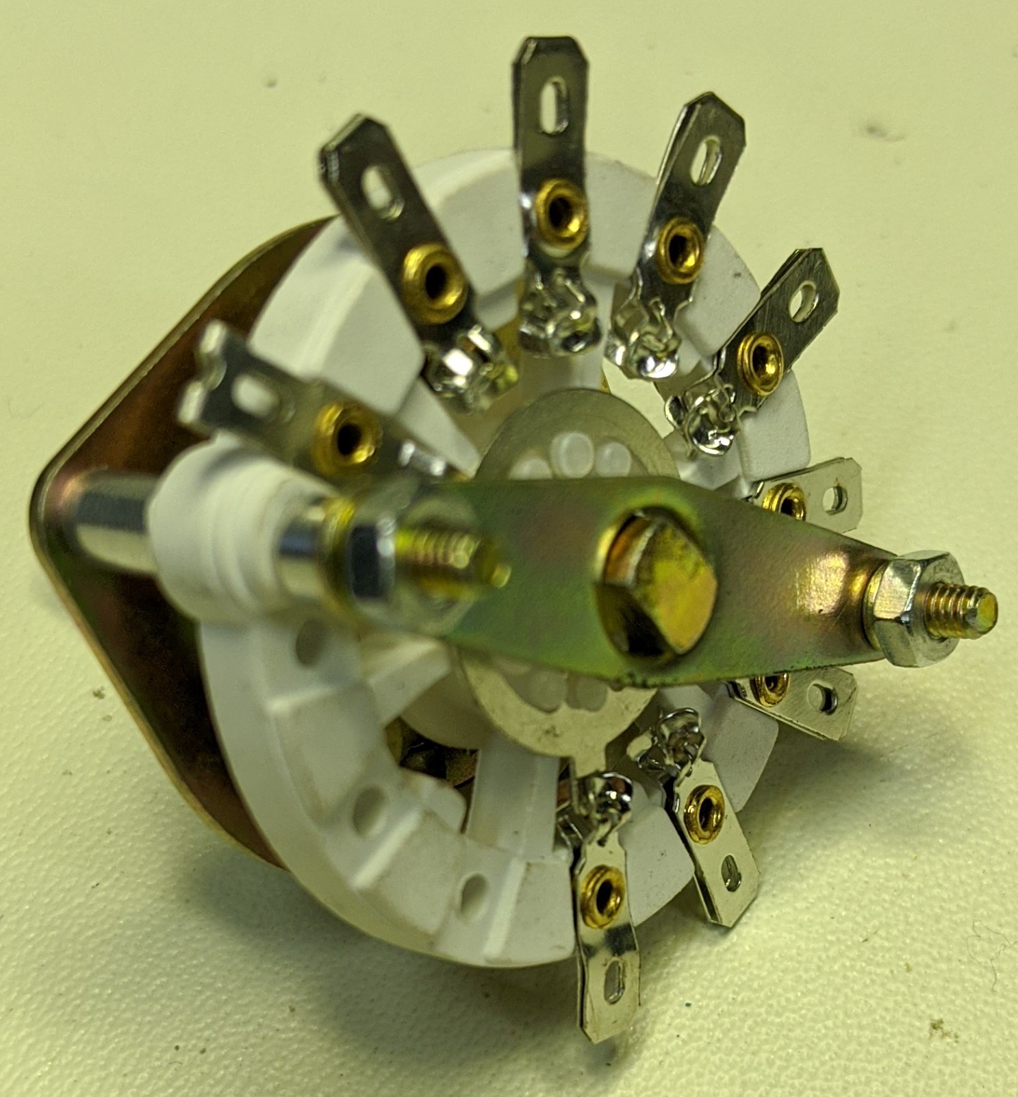
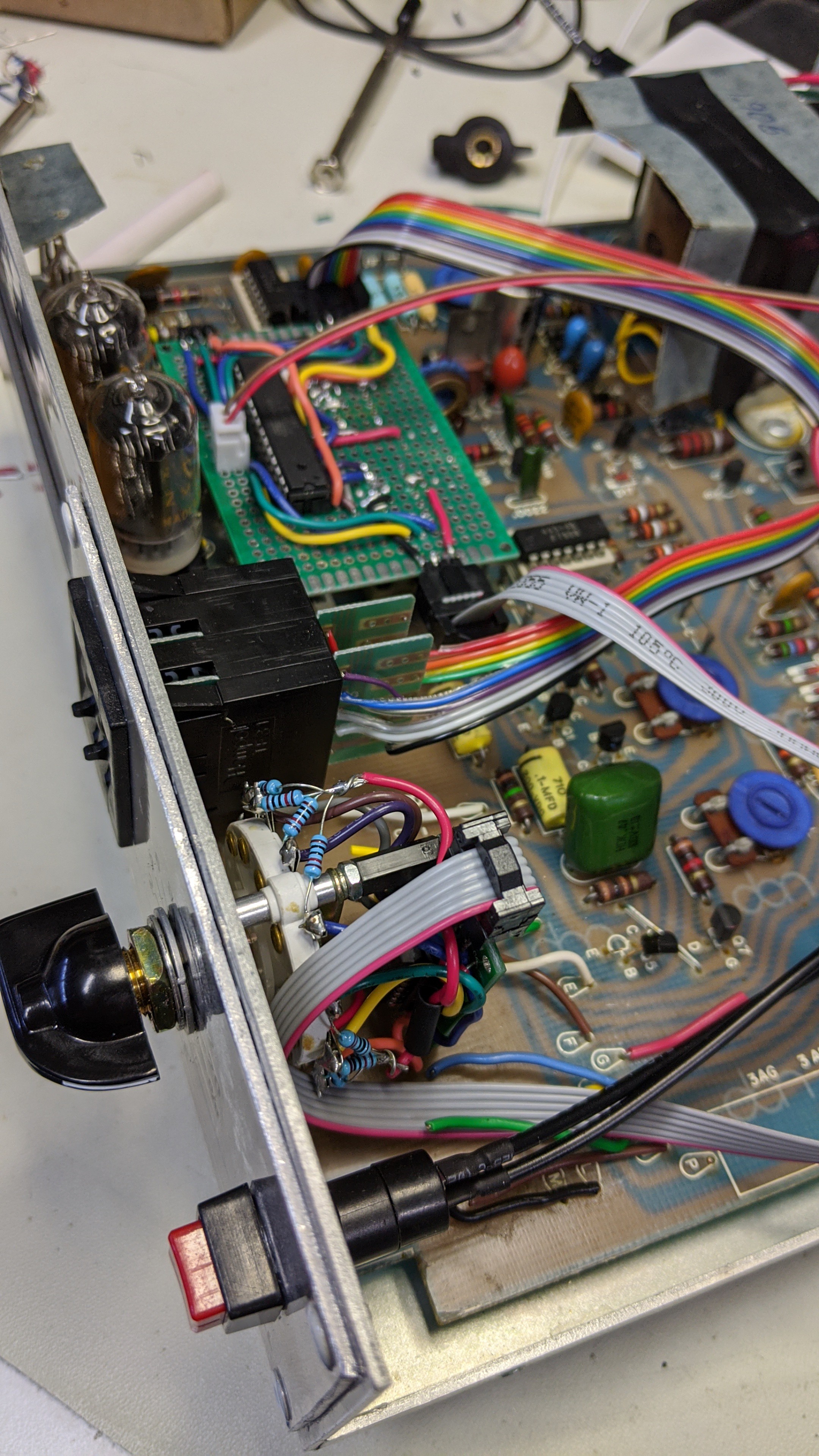
To reduce the conductors required for the internal connector cable and the input pins on AVR controller, I soldered up a small piece of proto-board with a 74HC148 8 Line to 3 Line Priority Encoder IC and 10K pull-up resistors on the inputs. Like the BCD encoded thumbwheel switch, this reduced the AVR input pins from 8 to 3. The little board screwed to the back of the switch and provided the 6 pin dual row IDC header for the cable connection to the controller board. The cable provides +5v, gnd, and the three conductors for the BCD encoded selected value.
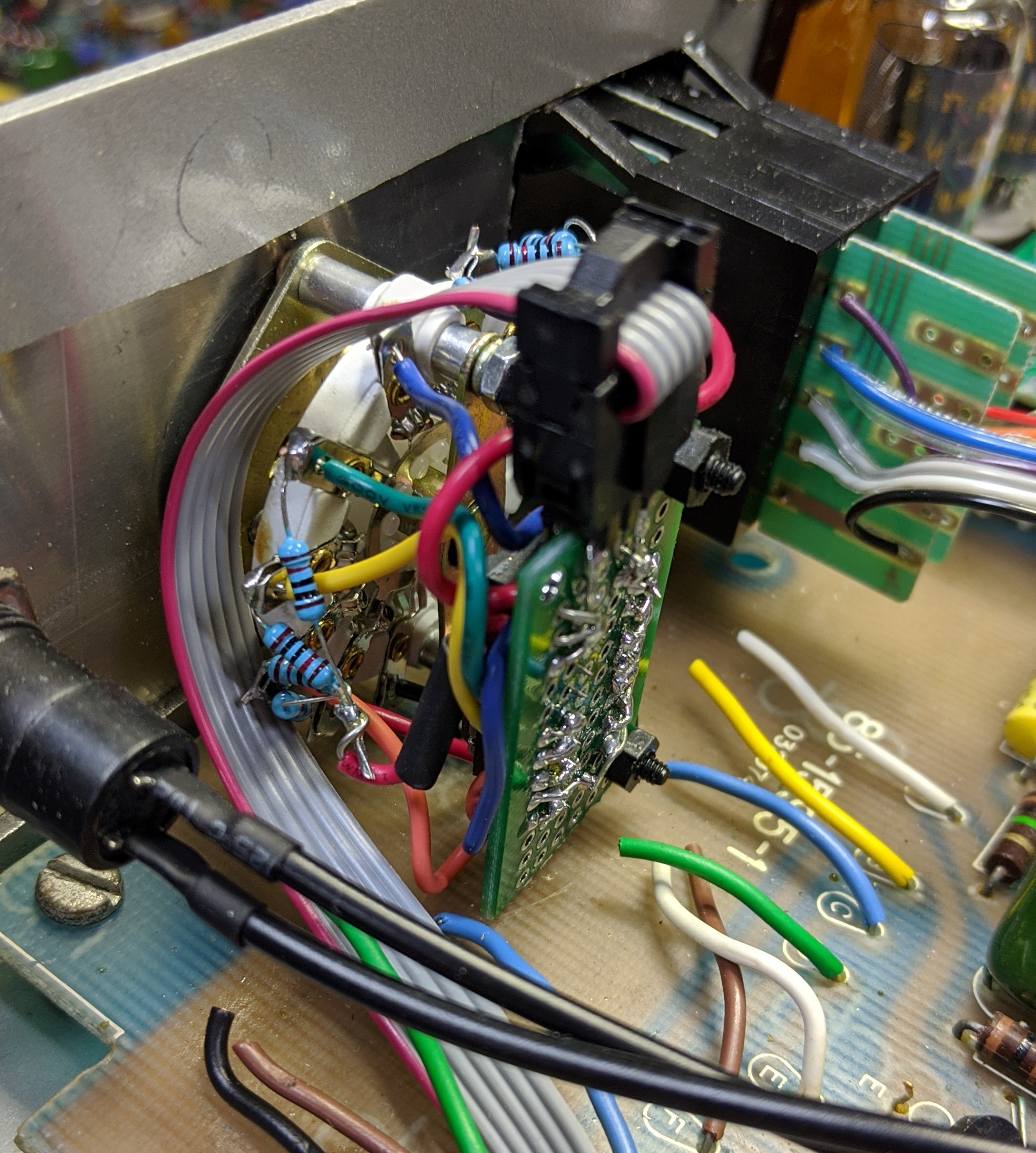
The three cables routed back to the controller board like so.
Discussions
Become a Hackaday.io Member
Create an account to leave a comment. Already have an account? Log In.